Front Door Adjustment
This guide explains how to adjust the front door on the Vision Miner 22IDEX V4 printer.
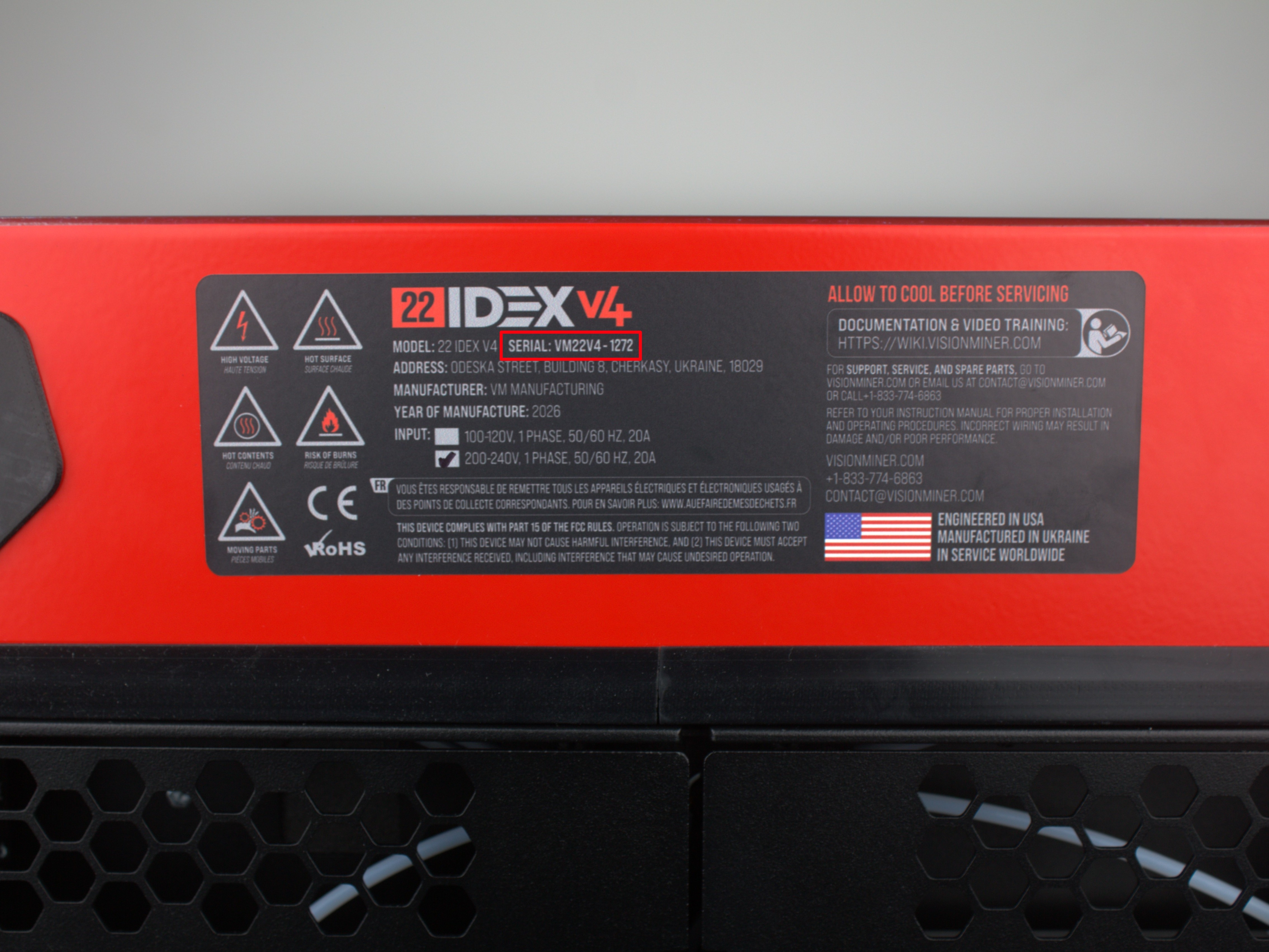
Serial Number Check
The adjustment method depends on your printer's serial number:
| Serial Number | Adjustment Method |
|---|---|
| Up to 291 | No adjustment available |
| 292 through 525 | Enclosure hinge adjustment |
| 526 and above | Door hinge adjustment |
Find your printer's serial number on the identification label. Use the table above to determine which adjustment method applies to your printer.
If your serial number is 291 or lower – door adjustment is not possible with the methods described in this guide. Contact support if alignment is needed.
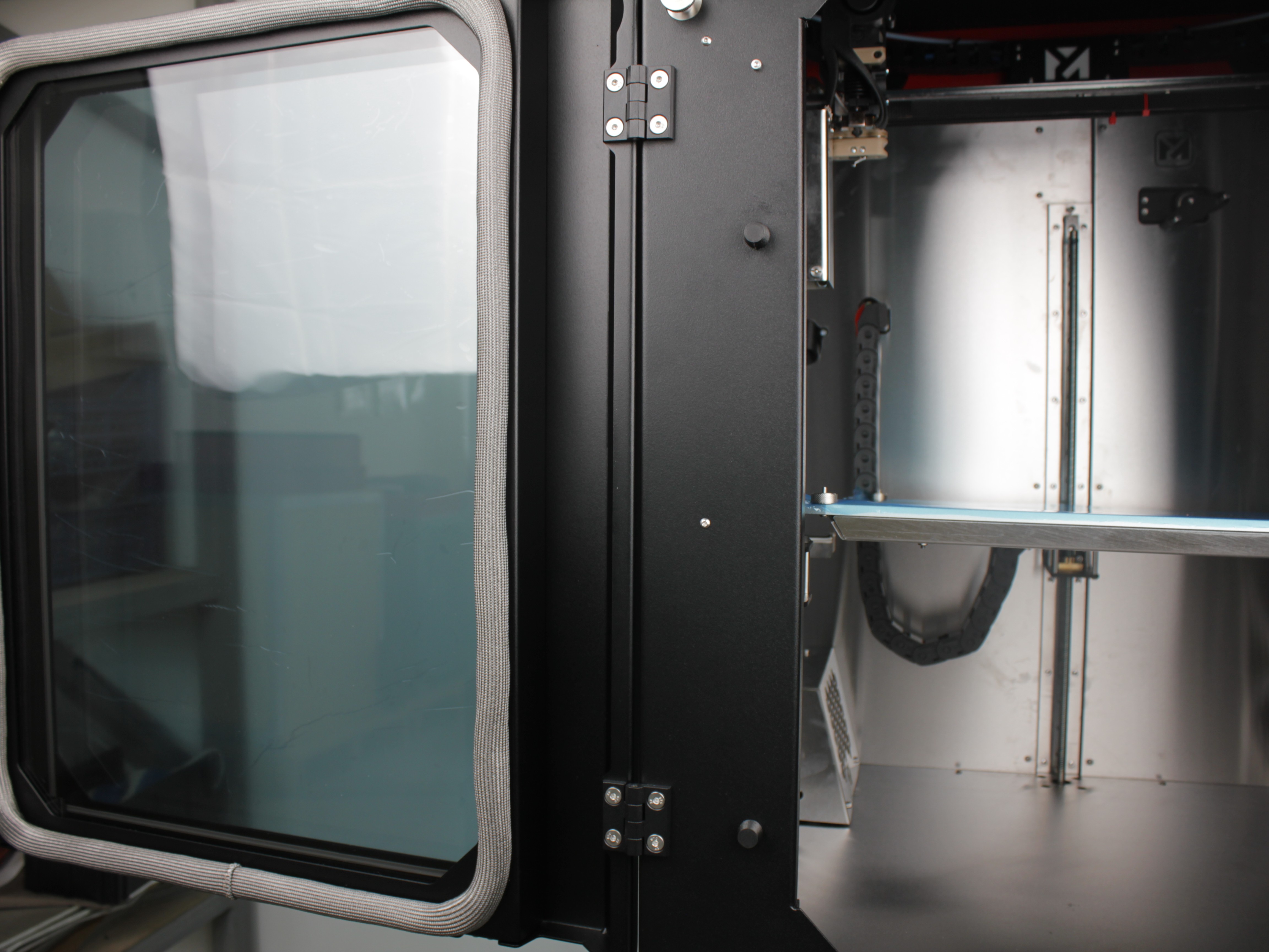
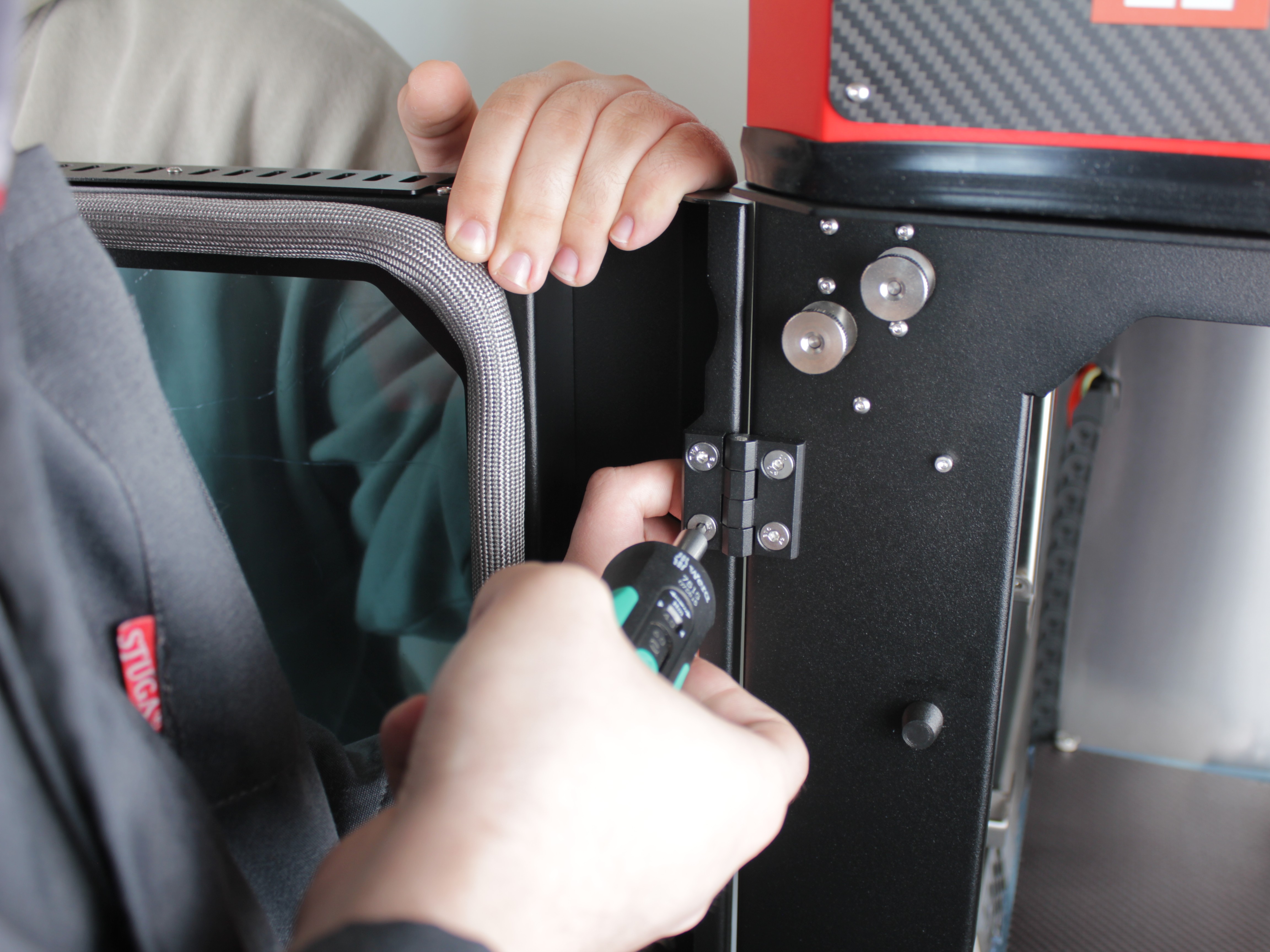
The front door is attached with two hinges (upper and lower):
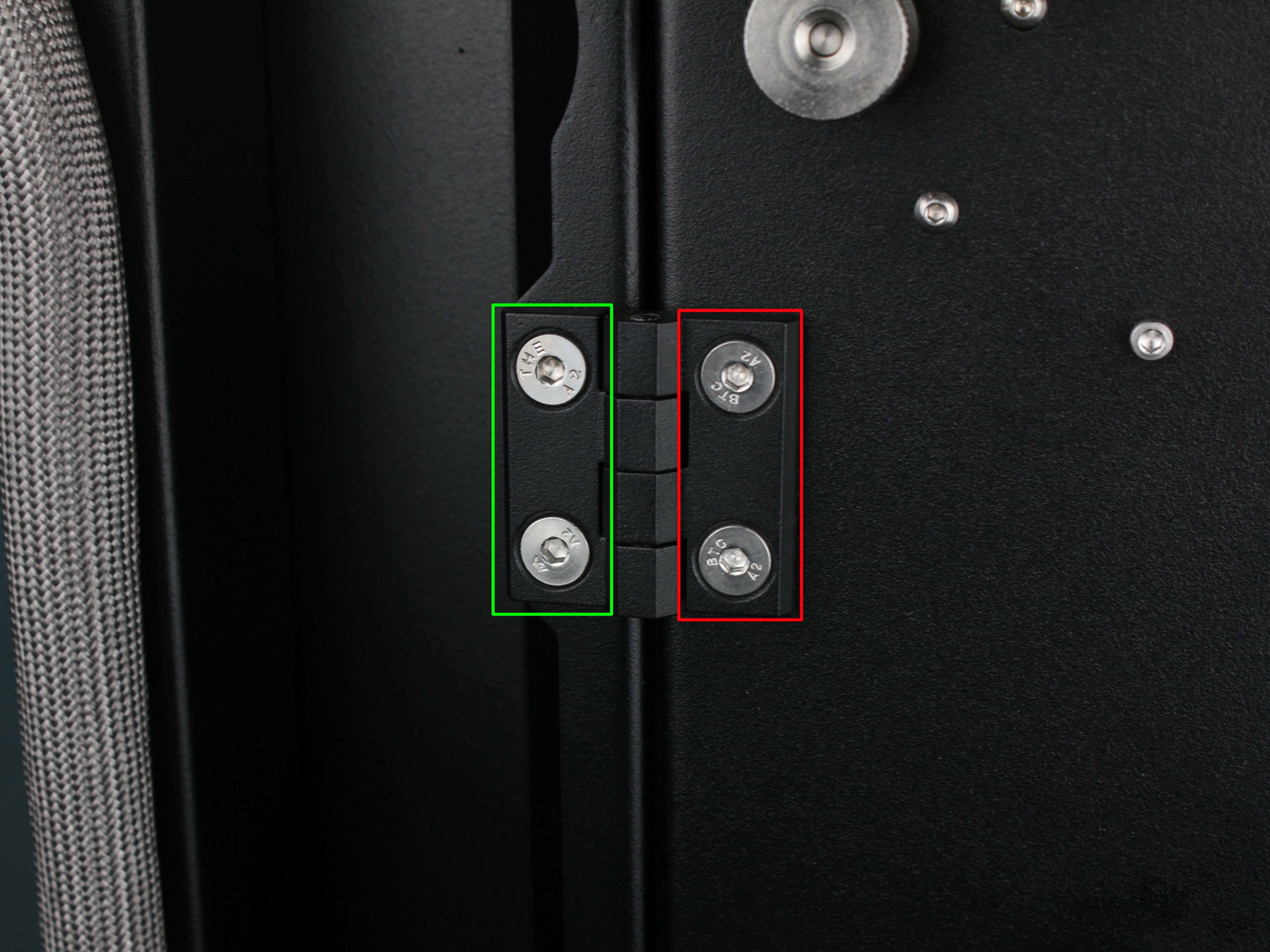
Depending on your printer's serial number, you will need to loosen screws in different locations:
- Serial 526 and above – loosen screws in the green box area (on the door side) on both hinges
- Serial 292 through 525 – loosen screws in the red box area (on the enclosure frame side) on both hinges
Required Tools
Both adjustment methods require the same tools:
- 7 mm wrench – to hold the nut on the back side of the hinge
- 3 mm hex bit – to tighten the screw
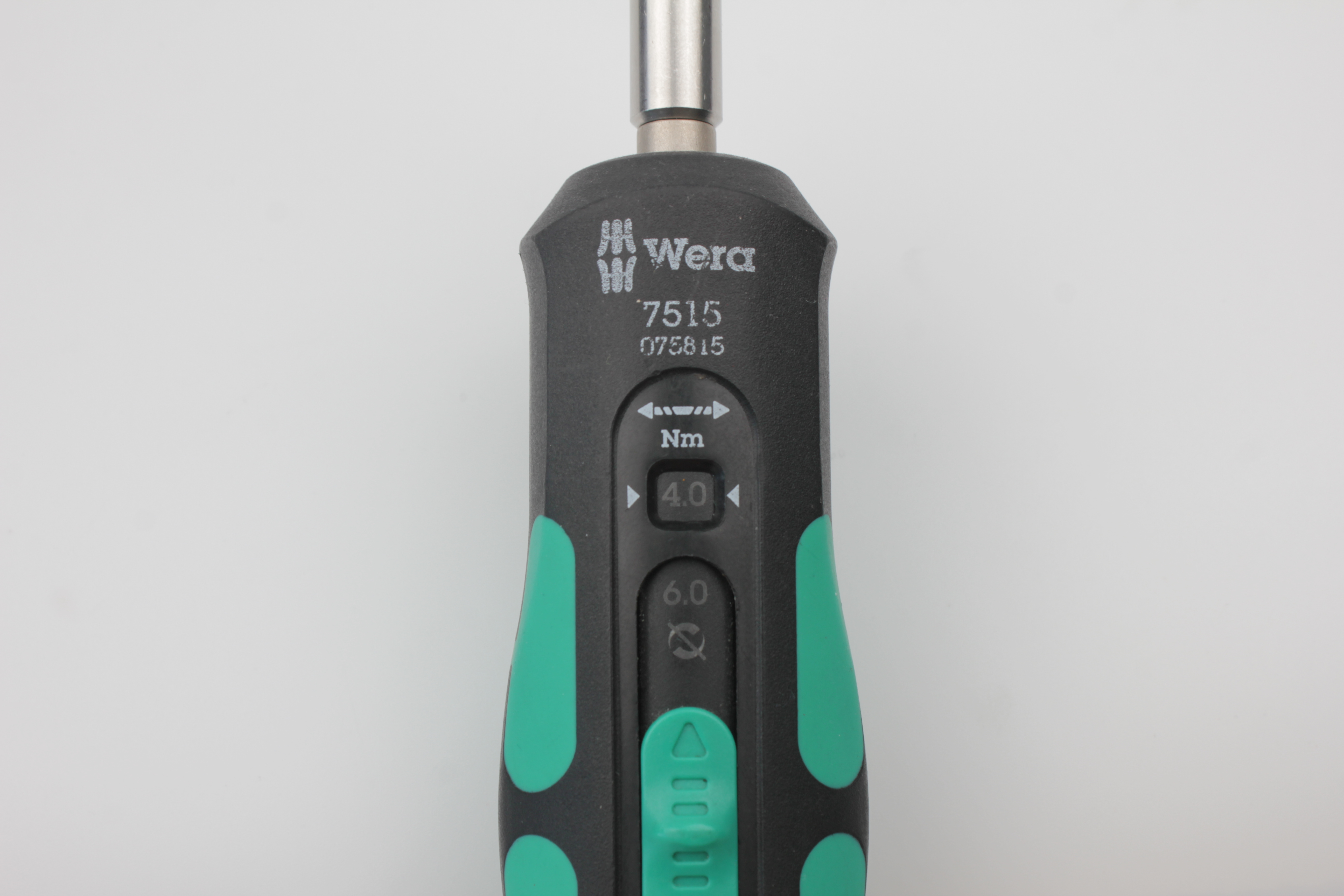
- Torque wrench set to 4.0 N·m (if available)
If you don't have a torque wrench
4.0 N·m is a small torque value. Tighten with moderate force in small equal steps. Over-tightening can damage threads or the door frame.
Door Hinge Adjustment (Serial 526 and above)
This procedure requires two people. One person supports and lifts the door, the other tightens the screws.
Procedure:
- Loosen hinge screws:
- On each hinge (upper and lower), leave one screw partially threaded: the top screw on the upper hinge and the bottom screw on the lower hinge
- Remove or loosen the other screws enough so the door can move freely
Nylon nuts – no thread locker
Hinge screws use nylon thread locking. Do not use chemical thread lockers (Loctite etc.) – they can damage plastic, glazing, or paint.
-
Tighten the top screw:
- Tighten the top screw on the upper hinge to 4.0 N·m
- If you don't have a torque wrench – tighten with moderate force
-
Lift the door as high as possible:
- One person holds the door, lifting it as high as possible
- The other person maintains this position while tightening the bottom screw
-
Tighten the bottom screw:
- While holding the door lifted, tighten the bottom screw on the lower hinge to 4.0 N·m
-
Check door position:
- Close the door and check for even gaps
- The door should not be twisted or sagging
-
Tighten remaining screws:
- Install the other two screws (middle screws on each hinge)
- Tighten them to 4.0 N·m in small equal steps, alternating sides
-
Verify alignment:
- Follow the Final Check procedure below to verify proper door alignment
Enclosure Hinge Adjustment (Serial 292-525)
For printers with serial numbers 292 through 525, the adjustment is performed on the enclosure-side hinges (where the hinges attach to the printer frame), not on the door-side hinges.
This procedure requires two people. One person supports and lifts the door, the other tightens the screws.
Procedure:
- Loosen enclosure-side hinge screws:
- Locate the hinge mounting points on the printer enclosure (frame)
- On each hinge (upper and lower), leave one screw partially threaded: the top screw on the upper hinge and the bottom screw on the lower hinge
- Remove or loosen the other screws enough so the door can move freely while supported
Nylon nuts – no thread locker
Hinge screws use nylon thread locking. Do not use chemical thread lockers (Loctite etc.) – they can damage the enclosure frame or hinge mounting points.
-
Tighten the top screw:
- Tighten the top screw on the upper enclosure hinge to 4.0 N·m
- If you don't have a torque wrench – tighten with moderate force
-
Lift the door as high as possible:
- One person holds the door, lifting it as high as possible
- The other person maintains this position while tightening the bottom screw
-
Tighten the bottom screw:
- While holding the door lifted, tighten the bottom screw on the lower enclosure hinge to 4.0 N·m
-
Check door position:
- Close the door and check for even gaps
- The door should not be twisted or sagging
-
Tighten remaining screws:
- Install the other two screws (middle screws on each hinge)
- Tighten them to 4.0 N·m in small equal steps, alternating sides
-
Verify alignment:
- Follow the Final Check procedure below to verify proper door alignment
Final Check
After completing the adjustment procedure, verify that the door is properly aligned:
-
Open and close the door several times:
- The door may settle or drop slightly after the initial adjustment
- If the door shifts noticeably, repeat the adjustment procedure
-
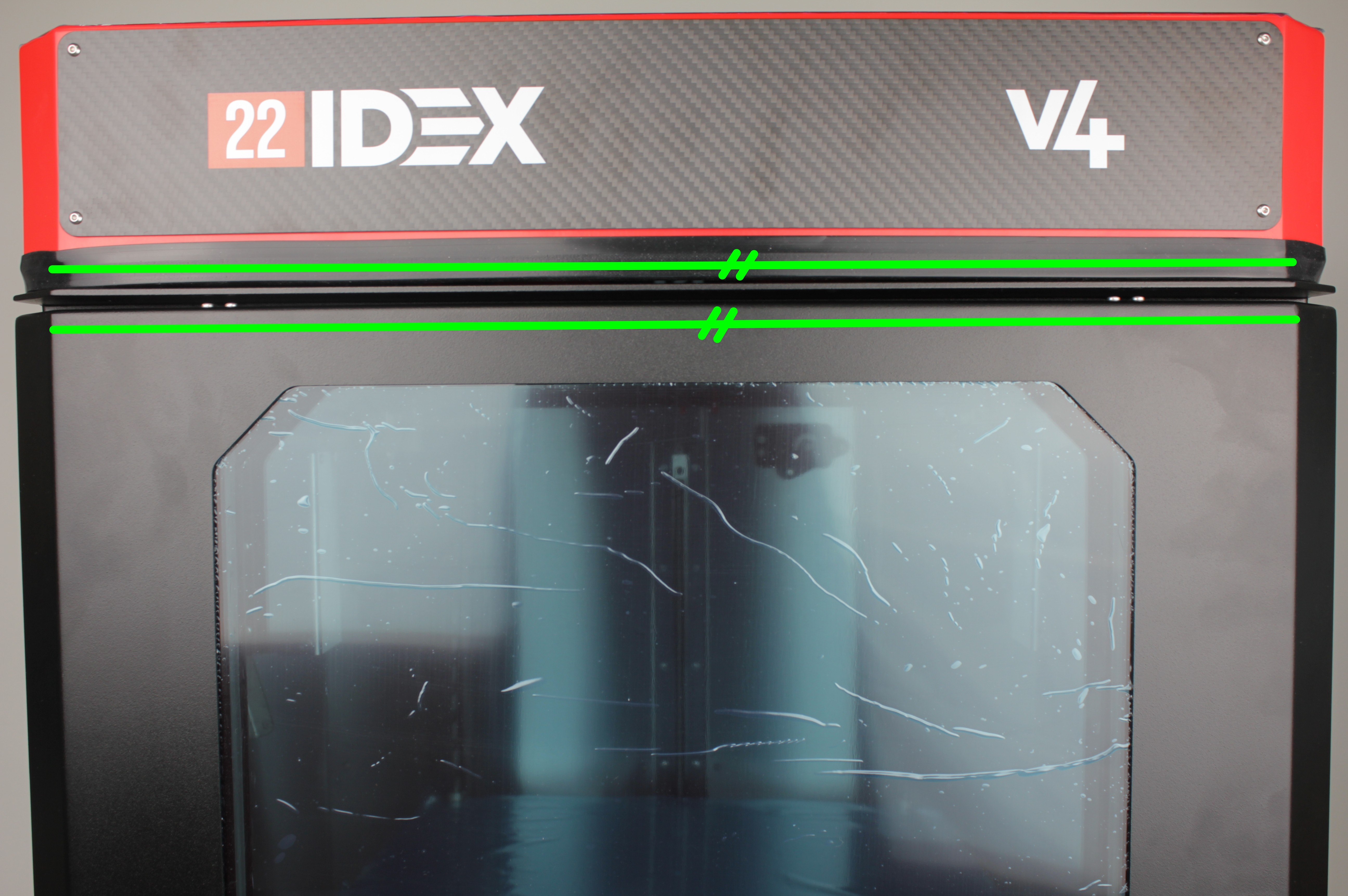
Check top edge alignment:
- Look at the top edge of the door and the top edge of the enclosure
- Imagine two parallel lines along these edges
- The lines should be parallel to each other
- The photo below shows green parallel lines indicating proper alignment
-
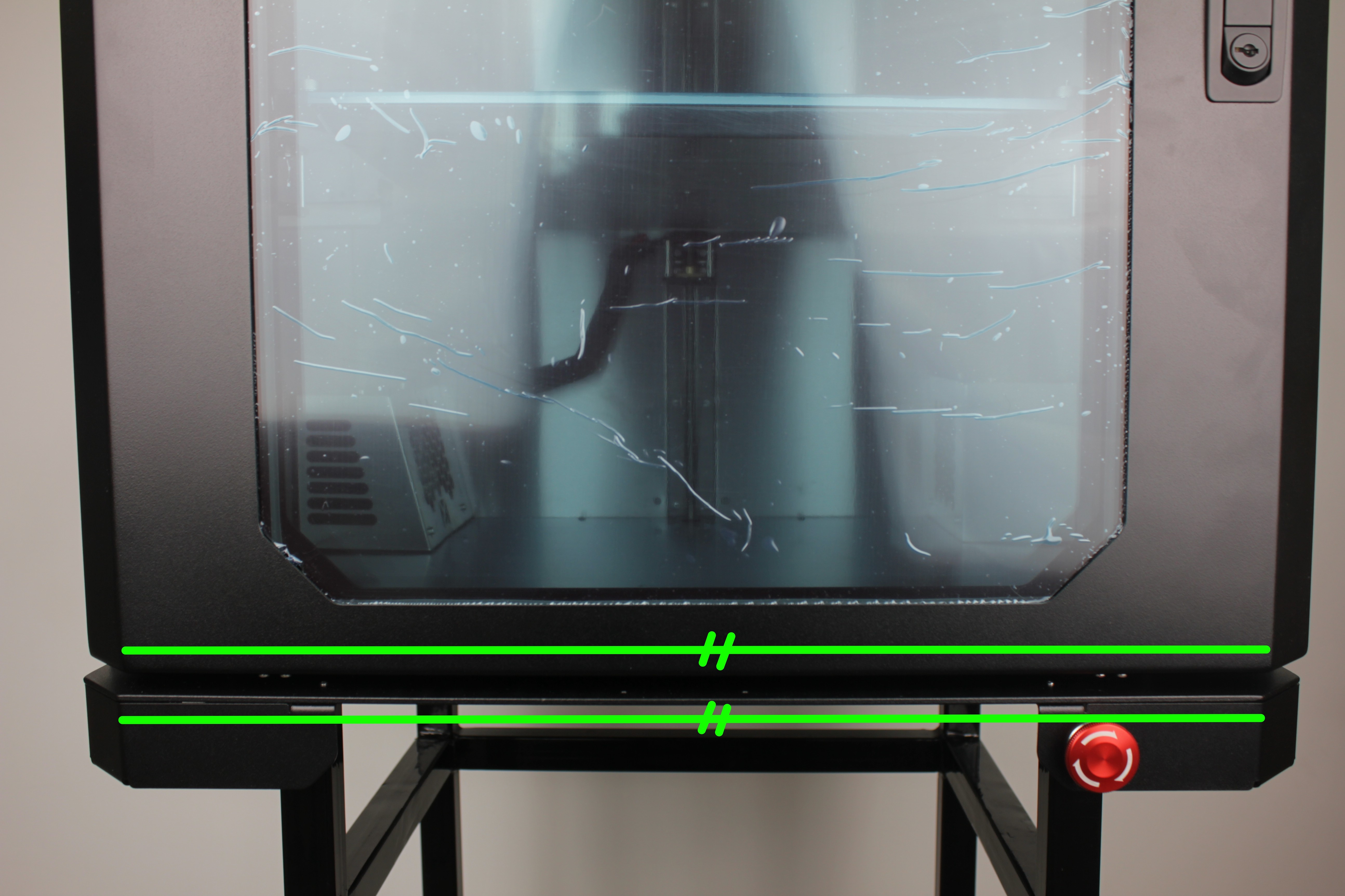
Check bottom edge alignment:
- Look at the bottom edge of the door and the bottom edge of the enclosure
- The edges should be parallel to each other, just like the top edges
- The photo below shows the bottom edge alignment
-
Verify smooth operation:
- The door should open and close smoothly without binding
- Gaps around the door should be uniform
If the door is not aligned after following this procedure, repeat the adjustment steps for your serial number range.
Frequently Asked Questions
Troubleshooting
Support
If you did not find an answer on this page, contact support.