Safety Before You Begin
Many maintenance and troubleshooting procedures on the Vision Miner 22IDEX V4 involve working with the printer's internal mechanics, electronics, and high-temperature components. All procedures described in this wiki are provided as informational examples and recommendations only - they are not directives or requirements. By choosing to follow any procedure, you acknowledge that you do so entirely at your own risk. Vision Miner assumes no liability for any damage, injury, or other consequence resulting from user-performed maintenance.
Before starting any procedure, read this article to understand the types of hazards involved and to assess whether you are comfortable performing the work yourself. If you are not confident in your ability to perform a procedure safely and correctly, contact Vision Miner support to arrange for a qualified professional technician to service your machine.
Each procedure article includes its own detailed safety warnings. This article gives you a bird's-eye view - so you can plan your work, prepare the right tools, and know what risks to expect before you open a single panel.
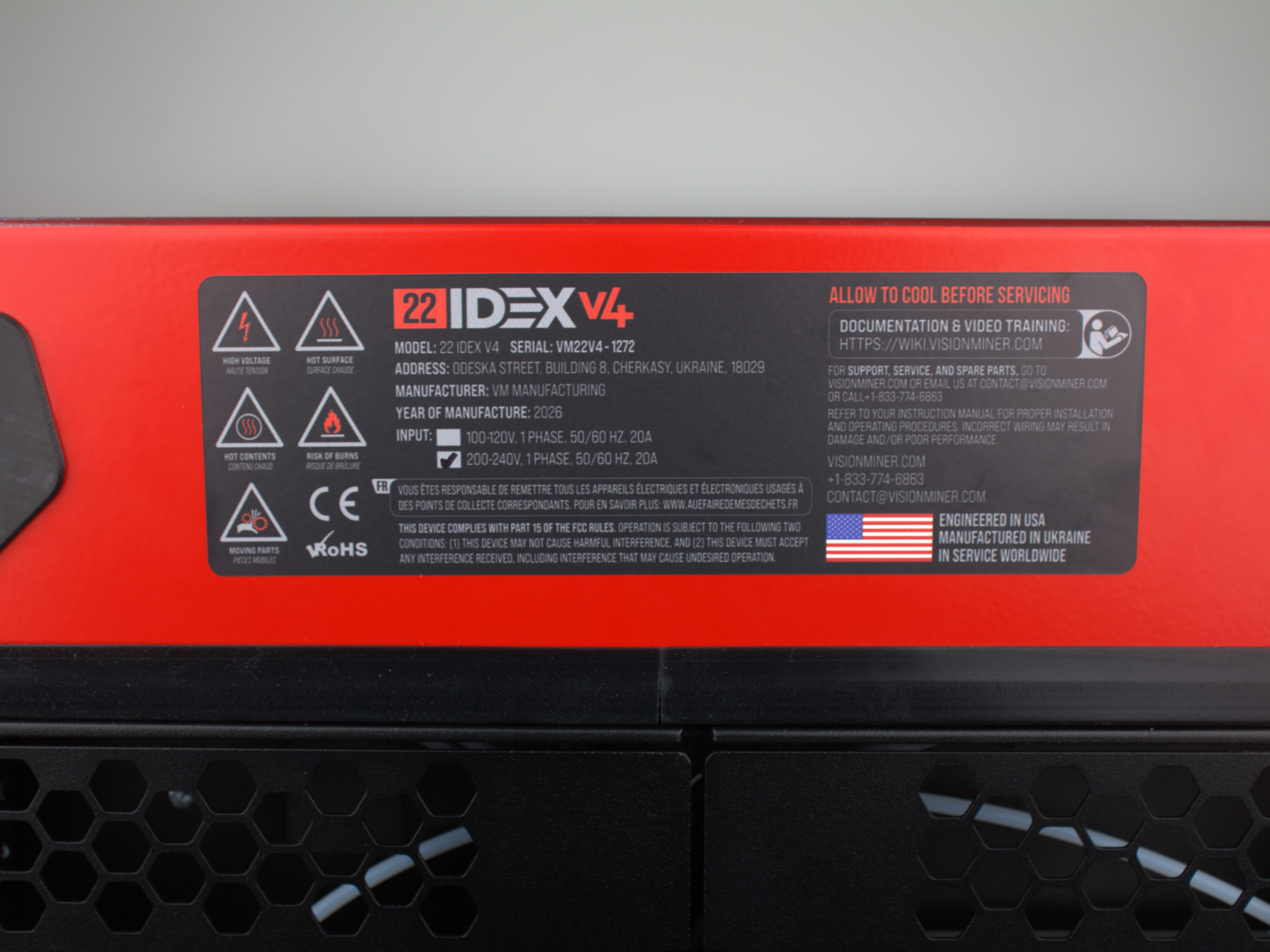
Rear Panel Safety Labels
The rear panel displays multiple safety warning labels. These labels mark high-voltage hazards, hot surfaces, and other risks inside the electronics compartment.
Read this article before opening the rear electronics bay
If you see these warning labels and need to work inside the rear electronics bay, read this entire Safety article first. The warnings cover lethal mains voltage, hot components, and other hazards that require preparation and protective measures.
Critical Safety Warnings
Mains voltage hazard - always unplug before servicing
The Vision Miner 22IDEX V4 operates on mains voltage (110 V / 220 V AC). Internal components carry lethal voltage while the printer is plugged in. Always unplug the printer from the wall outlet before performing any hardware work - the power button alone does not disconnect mains power.
Wait 60 seconds for capacitor discharge
After unplugging, wait at least 60 seconds for internal capacitors to discharge. Touching electronics before the discharge period can cause electrical shock.
High temperature components - let the printer cool
The nozzles can reach or exceed 500°C (932°F). The build plate can reach 200°C (392°F). The chamber temperature can reach 100°C (212°F) or more. Always let the printer cool down to ambient temperature and make sure all components are safe to touch before proceeding.
Incorrect assembly can permanently damage the printer
Incorrect assembly, wrong wiring, or skipped steps during maintenance can permanently damage the printer. All procedures are provided as recommendations only. Damage caused by user-performed maintenance that does not follow the documented procedures is not covered under warranty.
Contact support if uncertain
If at any point you feel uncertain about a procedure – stop and contact Vision Miner support. You may also arrange to have your machine serviced by Vision Miner.
Procedure Risk Categories
Maintenance and troubleshooting procedures on the Vision Miner 22IDEX V4 may involve one or more of the following hazard categories:
- Mechanical – work involving moving parts, gears, belt systems, bearings, motor brackets, pulleys, and heavy components. Includes disassembly, reassembly, lifting, and adjustment of the motion system.
- Electrical – work involving disconnecting or reconnecting cables, mainboard connectors, terminal blocks, power connections, and wiring. Includes any interaction with powered or previously powered components.
- Thermal – exposure to high-temperature components such as nozzles, heater blocks, the heated build plate, and the chamber heater. Surfaces can retain dangerous heat long after the printer is turned off.
- Chemical – handling of chemical substances such as isopropyl alcohol (IPA), adhesives, or use of open-flame tools (gas torch). Includes exposure to fumes and flammable materials.
- Damage – risk of permanent printer damage from incorrect assembly, improper torque, wrong cable orientation, or skipped steps.
The categories listed above are representative examples and are not exhaustive. Any given procedure may involve additional or overlapping hazards not described here. Always read the full procedure article and its specific safety warnings before starting work.
All procedures are provided as recommendations only
Every procedure in this wiki should be treated as a potentially consequential action. All procedures described in these articles are provided as recommendations and informational examples only - they are not directives. By choosing to follow any procedure, you do so entirely at your own risk. Vision Miner assumes no liability for any damage, injury, or other consequence resulting from user-performed maintenance. If you prefer to have maintenance performed by a qualified professional technician, contact Vision Miner support to arrange service. Only proceed with any procedure if you are confident and knowledgeable in the work being performed.
Electrical Hazards
The Vision Miner 22IDEX V4 has two internal power supplies:
| Power Supply | Voltage | Controlled by |
|---|---|---|
| Low-voltage PSU | 5 V DC | Always on while plugged in |
| High-voltage PSU | 24 V DC | Mainboard relay (power button) |
Both power supplies receive mains AC voltage (110 V or 220 V depending on your region). The mains side includes fuses, a solid-state relay (SSR), and wiring that carries lethal current.
What you need to know
- The power button does not disconnect mains power. It only disables the 24 V supply by holding the mainboard in reset. The 5 V supply - and all mains wiring - remains live. To fully de-energize the printer, unplug it from the wall outlet.
- Capacitors store energy after unplugging. Wait at least 60 seconds after unplugging before touching any internal components. This applies to every procedure that involves opening panels, disconnecting cables, or reaching into the electronics compartment.
- The 24 V system powers motors, heaters, and fans. The peak current draw is up to 20 A. Incorrectly connecting or disconnecting motor cables while the printer is powered on will destroy the stepper driver on the mainboard - this damage is permanent and not recoverable.
- Never service mains (HV) wiring yourself. The high-voltage wiring between the power supply, SSR, and the mainboard is for reference only. If you suspect a mains-side fault, contact Vision Miner support.
Procedures with electrical work
Below are examples of procedures that require disconnecting and reconnecting cables at the mainboard, terminal blocks, or motor connectors:
- Extruder Replacement – hotend heater wires, temperature sensor wires, fan wires, and the extruder motor cable are disconnected from terminal blocks using orange push-in release tabs.
- XY Motor Replacement – motor cables are disconnected directly from the motors in the rear electronics compartment.
- XY Pulley Replacement – same motor cable disconnection as the motor replacement procedure.
- Belt Replacement – fan wire disconnection at terminal block (Tool 0 only).
- Endstop Troubleshooting – endstop connectors on the mainboard are unplugged and inspected. Bending or forcing connector pins during inspection can permanently damage the socket.
- Z-Probe Troubleshooting – probe wiring traced from toolhead magnets to the distribution block/PCB; connectors inspected, removed, and reseated; optional multimeter testing.
- Under-Extrusion Troubleshooting – hotend cable disconnection for partial toolhead disassembly; in severe cases, motor cable troubleshooting with driver isolation.
- Unboxing and Initial Setup – the first power connection. The printer must be connected to a properly grounded 20 A outlet. An ungrounded outlet or a damaged power cord creates a shock hazard and can damage electronics.
Never hot-swap motor connections
Always power off the printer and unplug it from the wall outlet before connecting or disconnecting any cable. Hot-swapping motor connections while the printer is powered on will permanently destroy the stepper driver on the mainboard.
Photograph connectors before disconnecting
Before disconnecting any wires, photograph the connector orientation and wire order. Incorrect reconnection can damage the mainboard or cause short circuits.
Thermal Hazards
The Vision Miner 22IDEX V4 is designed for high-performance materials and operates at temperatures far beyond typical desktop printers.
| Component | Maximum temperature |
|---|---|
| Nozzle / heater block | 500°C (932°F) or more |
| Heated bed | 200°C (392°F) or more |
| Chamber air | 100°C (212°F) or more |
| Chamber heater element | 180°C (356°F) or more |
These temperatures cause severe burns on contact. Even after the printer is turned off, metal components retain heat for a significant time.
Procedures with thermal hazards
- Under-Extrusion Troubleshooting – diagnosis requires the printer to be heated (extrusion tests, fan checks). Nozzle cleaning with a gas torch involves open flame and red-hot metal.
- Z-Probe Troubleshooting – some diagnostic steps run with the printer powered on and heated.
- NPA Application – the hot application method involves working near a build plate heated to 120–180°C (248–356°F).
- Material Calibration – test prints run at full operating temperatures. Parts and the bed are hot immediately after printing. Handling test pieces too early causes burns.
- Endstop Troubleshooting – the nozzle and bed may retain heat from recent use.
- HEPA Filter Replacement – the chamber heater on the opposite side of the enclosure may still be hot.
- Filament Jamming / Heat Creep Troubleshooting – diagnostic steps require the hotend to be heated to printing temperature.
- Large Spool Setup (V4) – requires the printer to be powered off, but the nozzles and bed may retain heat if recently used. Working inside the enclosure while surfaces are still warm can cause burns.
Never assume components are cool after shutdown
Never assume a component is cool just because the printer is turned off. Metal components (nozzle, heater block, bed) retain dangerous heat for 15–30 minutes after shutdown. Always verify the temperature in the Web Interface or let the printer sit for at least 30 minutes before touching anything inside the enclosure.
Mechanical Hazards
Many procedures require partial or full disassembly of the printer's motion system – removing panels, brackets, belts, motors, and toolhead components. Mechanical work carries two main risks: pinch injuries from moving parts, and damage to the printer from incorrect reassembly.
What you need to know
- Moving parts can pinch fingers. The XY gantry, toolheads, and belt tensioners can move unexpectedly if not fully powered off. Keep hands clear of the motion system whenever testing movement.
- Belt routing is specific to this machine's kinematics. Incorrect belt routing – twisted belts, wrong tooth orientation, or belts that don't fully wrap the motor pulley – will cause print defects or damage the motion system.
- Screw sequences matter. Several procedures use cross-pattern tightening, threadlocker, and specific torque. Skipping threadlocker or tightening in the wrong order causes screws to loosen during printing, which leads to calibration drift or component failure.
- Small parts can damage the bed. Dropped screws, washers, or tools can scratch. Always cover the bed with a protective cloth before starting mechanical work above it.
High-complexity procedures
These procedures involve the most extensive mechanical disassembly and require the most care:
- XY Motor Replacement – removing the top cover, cover limiter, disconnecting belts, removing motors from bracket, transferring pulleys, and full reassembly with threadlocker. Two-motor bracket must go back in the correct orientation.
- XY Pulley Replacement – same disassembly as motor replacement, plus precision pulley positioning on the motor shaft.
- Extruder Replacement – full toolhead teardown: fan shroud, cable cover, hotend assembly, terminal block holder, motor+extruder separation, and reassembly with threadlocker.
- Belt Replacement – multi-section procedure covering Y-axis and both tool belts. Tool 0 requires removing the print head assembly; belt length must be cut precisely.
Lower-complexity procedures that still carry damage risk
Don't let the word "lower" mislead you – these procedures are simpler, but careless execution still leads to real damage:
- Unboxing and Initial Setup – the printer weighs 80 kg (≈ 175 lbs). Two people minimum for lifting. The crate contains transport zip ties on the belts – cutting them carelessly can nick the belts, requiring immediate replacement. Build plate securing screws must be loosened correctly (3–4 mm of thread remaining), not removed. The power cord must go into a grounded 20 A outlet – an ungrounded or undersized outlet creates a fire and shock hazard.
- Belt Tensioning – over-tensioning belts accelerates bearing and motor shaft wear. Under-tensioning causes layer shifting and dimensional errors. The target is exactly 65 Hz – not "tight enough" by feel.
- Macros (Firmware Scripts) – running built-in macros seems safe because it's just pressing a button in the Web Interface. But the Movement Without Homing macro disables position verification, allowing the toolheads to collide with the frame, the bed, or each other. Reset Bed Level intentionally stalls the Z motors – normal grinding is expected, but running it without understanding the process can cause alarm or misdiagnosis.
- Filament Breaks Inside Tube – the fix involves cutting zip ties on the cable chains. Cutting the wrong zip tie or nicking the PTFE tube creates a new problem. The article also warns that the freed PTFE tube may rub against the top lid insulation, causing gradual wear.
- HEPA Filter Replacement – the filter bracket uses hook-shaped tabs. Forcing the bracket in or out without properly unhooking the tabs can bend or break the mounting points.
Run auto-calibration after mechanical work
After any mechanical work on the motion system (belts, motors, pulleys, idlers), you must run the full auto-calibration procedure before printing. Skipping calibration after mechanical work will produce inaccurate prints and may mask assembly errors.
Chemical Hazards
These procedures involve chemical substances that require ventilation and careful handling:
Isopropyl alcohol (IPA)
Used in NPA application and cleaning procedures.
- Flammable. IPA ignites easily. Keep it away from heat sources, open flames, and the printer's heated components. Never apply IPA on a hot build plate – the hot application method uses diluted NPA, not pure IPA on a heated surface.
- Vapors. Work in a well-ventilated area. Prolonged inhalation of IPA vapors can cause dizziness and headache.
Gas torch (butane)
Used in the Under-Extrusion Troubleshooting guide for severe nozzle clog removal (torch cleaning method).
- Open flame. Work on a fireproof surface. Keep flammable materials and solvents (including IPA) away from the work area.
- Red-hot metal. The nozzle glows red during torch cleaning. Use heat-resistant gloves and pliers. Never place a glowing nozzle on a flammable surface.
- Thermal shock. The procedure includes quenching a red-hot nozzle in water. Be prepared for steam and use eye protection.
Never use a gas torch near the printer or solvents
Never use a gas torch near the printer or near IPA/solvents. Perform torch cleaning on a separate fireproof workbench, away from the printer.
Before You Start Any Procedure
Use this checklist before beginning any maintenance or troubleshooting procedure:
- Read the entire procedure article first. Do not start disassembly before you have read all the steps, including reassembly. Know what tools you need and what the end state should look like.
- Turn off and unplug the printer. For any procedure that involves touching hardware – always unplug from the wall outlet, not just press the power button.
- Wait 60 seconds for capacitors to discharge.
- Let the printer cool. If it was recently in use, wait at least 30 minutes or verify all temperatures read below 40°C (104°F) in the Web Interface before unplugging.
- Cover the build plate if working above the bed. A soft cloth prevents scratches from dropped parts.
- Photograph everything before disconnecting. Take photos of wire positions, connector orientations, and component layouts. You will need these during reassembly.
- Prepare all tools and parts listed in the procedure's Tools and Materials section. Having everything ready prevents interruptions mid-procedure.
- Work in a well-lit, clean area. Small screws and washers are easy to lose. Use a magnetic tray or small container.
- Run auto-calibration after mechanical work. Any procedure that touches the motion system (belts, motors, pulleys, idlers, toolheads) requires recalibration before printing.
Support
If you could not find an answer here, reach out to our support team.