Y-Endstops
This guide covers the installation and configuration of Y-axis endstops for Vision Miner 22IDEX V2 printers. Y-endstops improve homing accuracy and ensure proper crossbar alignment by providing precise position feedback during the Y-axis homing process.
Before you begin - safety and risk
Read the Safety - Before You Begin article to understand the hazards involved in working on the Vision Miner 22IDEX V4 - including electrical, thermal, mechanical, and chemical risks. All procedures in this wiki are provided as recommendations only. By choosing to follow any procedure, you do so at your own risk.
Required Tools and Parts
Tools:
- Hex 2mm Allen key
- Hex 2.5mm Allen key
- PH2 Phillips screwdriver
- Y-EndStop Tool STL (3D printed)
Parts:
- 2x Y-EndStop
- 4x M3 Screws
- 4x M3 Nuts
Y-Endstop Installation
-
Power off the machine. Ensure the printer is turned off and unplugged from the power source.
-
Wait for components to cool. Allow all heated components to reach room temperature to avoid burns.
-
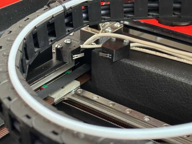
Position the first endstop. Place the left Y-endstop in the front left corner of the printer, ensuring it is oriented correctly with the open side down and metal plate facing the center.
- Use the printed tool to hold the nut. Insert the Y-EndStop Tool (3D printed) to hold the M3 nut in place during installation.
- Secure the first endstop. Use the provided M3 screws to attach the left endstop. Tighten the screws securely while the printed tool holds the nut in place.
- Position the second endstop. Place the right Y-endstop in the front right corner, ensuring it is mirrored from the left endstop with the open side down and metal plate facing the center.
- Secure the second endstop. Use the printed tool and M3 screws to attach the right endstop in the same manner as the left.
- Verify endstop orientation. Confirm both endstops are mirrored, with open sides down and metal plates facing each other. The endstops should be positioned to contact the backs of the tool heads during homing.
Move Extruder Screws (If Needed)
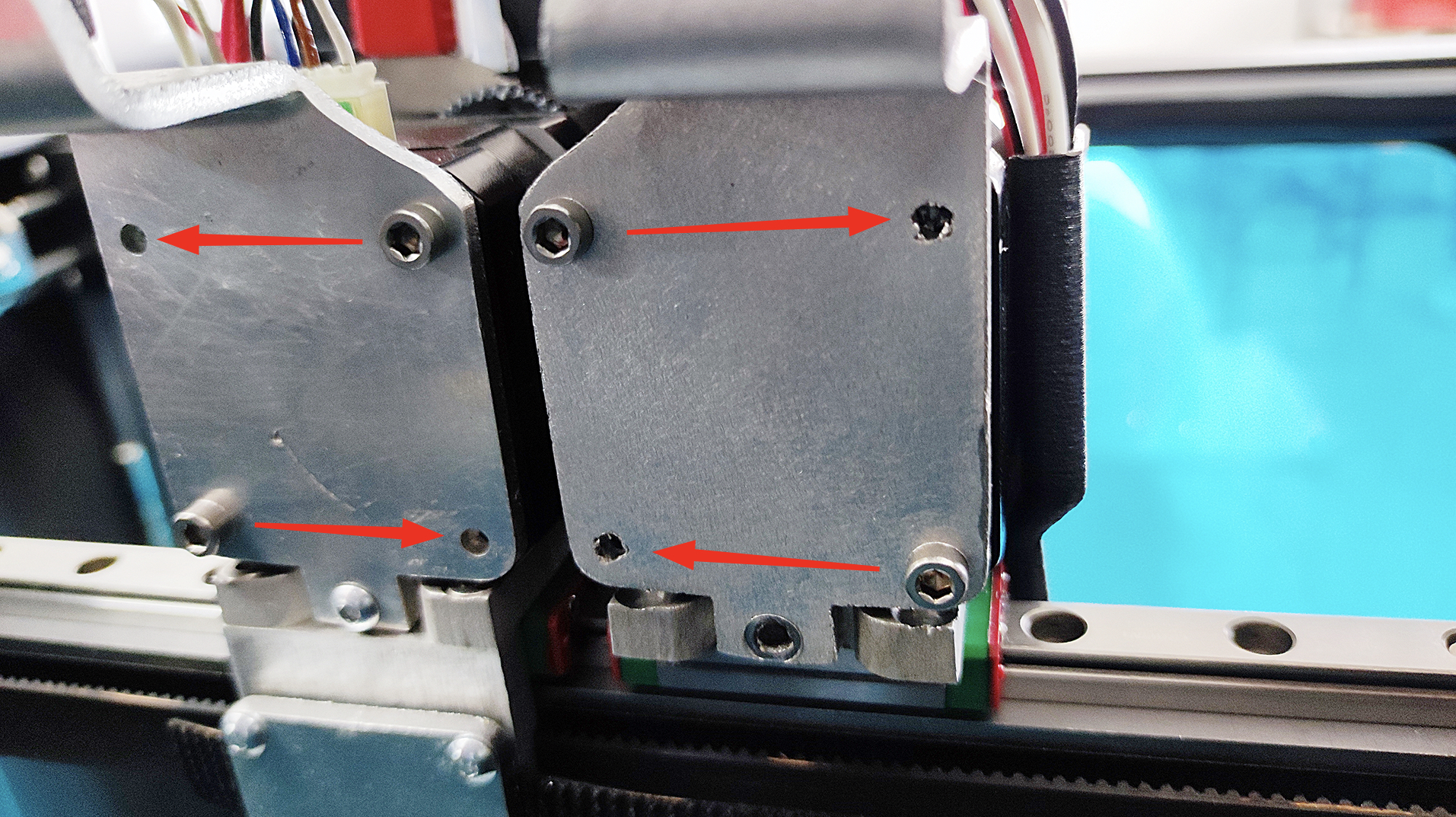
The bolts on the backs of the tool heads must be positioned diagonally, with the upper screws closer to the printer's outer sides and the lower screws closer to the middle. If your tool heads have screws in the wrong positions, follow these steps.
- Remove the aluminum plate. Use the 2.5mm hex Allen key to remove the two upper screws securing the aluminum plate on the back of the tool head. Use the 2mm hex Allen key to remove the bottom screw, freeing the aluminum plate completely.
- Loosen the first extruder screw. Carefully loosen one of the screws on the extruder using the PH2 Phillips screwdriver. Be cautious not to strip the screw.
- Relocate the first screw. Move the loosened screw to the opposite hole diagonally (either horizontally or vertically) to achieve the diagonal pattern.
- Relocate the second screw. Repeat the loosening and relocation process for the second screw, moving it to the remaining free hole to complete the diagonal pattern.
- Reattach the aluminum plate. Position the aluminum plate back onto the tool head, aligning the mounting holes.
-
Lightly tighten all screws. Lightly tighten the bottom screw using the 2mm hex Allen key. Lightly tighten the two upper screws using the 2.5mm hex Allen key. Verify the plate is properly aligned.
-
Securely tighten all screws. Once alignment is confirmed, securely tighten all three screws on the tool head.
-
Repeat for the second tool head. If the second tool head also requires screw relocation, repeat steps 9-15 for that tool head.
Connect Wiring
- Locate the Y-endstop wiring. Identify the wiring for the Y-endstops in your printer's wiring harness.
- Connect the left endstop. Plug the left Y-endstop wire connector into the left endstop.
- Connect the right endstop. Plug the right Y-endstop wire connector into the right endstop.
- Verify secure connections. Ensure both endstop connectors are fully seated and secure.
Update Firmware
- Update to Y-endstop compatible firmware. After installation, you must update the firmware to the latest version compatible with V2 printers equipped with Y-EndStops. Follow the firmware update guide for detailed instructions.
- Power on the machine. After firmware update, reconnect power and turn on the machine.
Verify Homing Process
- Home all axes. Open the Web Interface, navigate to the Dashboard, and click "Home All" to initiate the homing sequence.
- Observe the Y-axis homing sequence. The homing process should proceed as follows:
- The crossbar moves to the front end, then slightly back, and forward again to calibrate against both Y-endstops.
- The crossbar moves to the maximum back position.
- The left head moves to the far left (X-axis), and the right head moves to the far right (U-axis).
- The heads move slightly away from the sides.
- The printer aligns the crossbar along the Y-axis - one side may adjust slightly forward or backward.
- The printer re-homes the X and U axes if necessary.
- Verify no excessive crossbar skew. When homing the Y-axis, observe the crossbar correction. It should not twist more than 1 mm. If the crossbar adjustment exceeds the allowed limit, you will see an error message in the Web Interface.
- Listen for unusual sounds. The homing process should be smooth without any grinding, clicking, or unusual noises. If you hear unusual sounds or observe abnormal movements, stop the machine immediately and check the installation.
FAQ
Troubleshooting
Support
If you could not find an answer here, reach out to our support team.