Chamber Heater
This guide provides step-by-step instructions for replacing the Chamber Heater element in the Vision Miner 22 IDEX printer. The Chamber Heater maintains elevated ambient temperature within the build enclosure, crucial for printing high-temperature materials like ABS, PC, and PEEK. This procedure involves working with mains voltage electrical connections.
Before you begin - safety and risk
Read the Safety - Before You Begin article to understand the hazards involved in working on the Vision Miner 22 IDEX printer – including electrical, thermal, mechanical, and chemical risks. All procedures in this wiki are provided as recommendations only. By choosing to follow any procedure, you do so at your own risk.
Tools & Materials
- Replacement Chamber Heater
- PH2 Phillips Screwdriver
- Flathead Screwdriver (appropriate size for electrical terminal screws)
- 2.5 mm Hex Driver (for optional heater cover removal)
- 7 mm Wrench (for optional heater cover removal)
- Wire Cutters
- New Zip Ties (small)
- Thermal Paste (e.g., Boron Nitride Paste)
1. Preparation and Safety
Document connections
Before disconnecting any wires, carefully note their exact positions on the terminals (Relay, Distribution Block). Taking clear photos is highly recommended. Incorrect wiring upon reassembly can lead to component damage, malfunction, or safety hazards.
- VERIFY POWER OFF: Double-check that the printer is switched off AND unplugged from the mains power source.
- Cool Down: Ensure all components are at room temperature.
- Gather all necessary tools and the new Chamber Heater unit.
- Ensure adequate lighting and clear access to both the inside of the print chamber and the rear electrical compartment.
- Open or remove the rear access panel/door(s) to expose the electrical compartment containing the relay and distribution blocks.
2. Disconnecting the Old Heater
Electrical Disconnection (Rear)
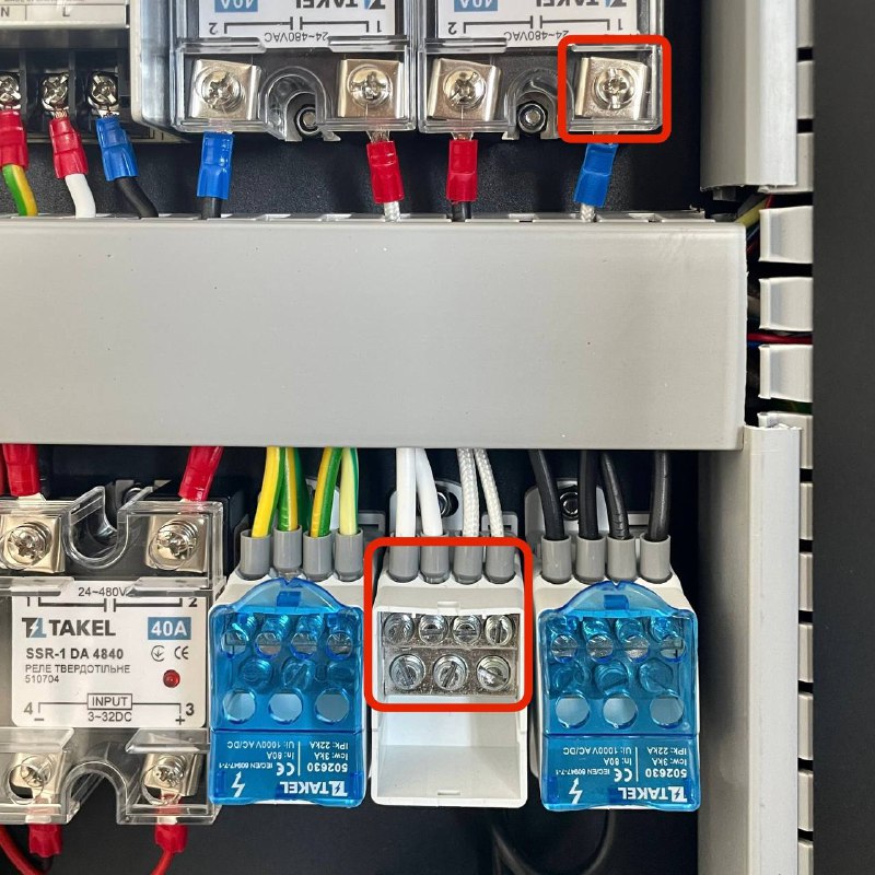
- Identify Heater Wires: Locate the power cables originating from the Chamber Heater element. Trace them to where they connect inside the rear electrical compartment. They typically connect to a Solid State Relay (SSR) and a Power Distribution Block.
-
Document Connections: (CRITICAL STEP) Take clear photos or draw a precise diagram showing exactly which terminals the Chamber Heater wires are connected to on both the Relay and the Distribution Block. Note wire colors or any polarity markings if present.
-
Disconnect Wires: Using the Flathead Screwdriver, carefully loosen the terminal screws for the Chamber Heater wires on the Relay and the Distribution Block. Gently pull the wires out of the terminals.
-
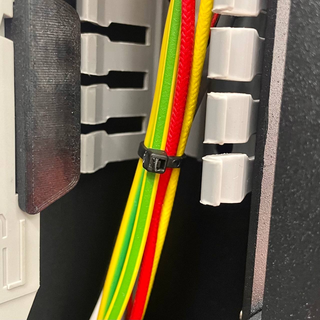
Cut Zip Ties: Using Wire Cutters, carefully snip any zip ties that are bundling the Chamber Heater cables with other wiring within the rear compartment. Free the cables so they can be pulled through later. Be cautious not to cut adjacent wires.
Heater Removal (Inside Chamber)
- (Optional but Recommended for Access) If the Chamber Heater has a protective metal cover, remove it now using the 2.5 mm Hex Driver and 7 mm Wrench. Keep the cover and its fasteners safely aside.
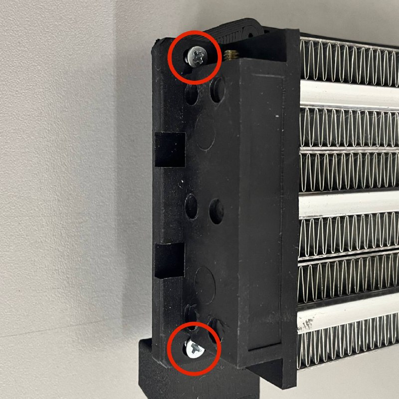
- Unscrew Heater: Using the PH2 Phillips Screwdriver, remove the screws that mount the main Chamber Heater unit to its support brackets or holders inside the print chamber.
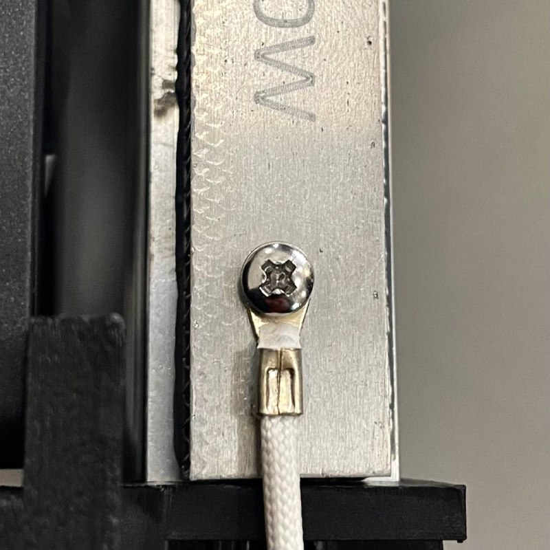
- Disconnect Temp Sensor: Locate the temperature sensor attached to the body of the Chamber Heater. Using the PH2 Phillips Screwdriver, remove the screw securing the sensor. Carefully detach the sensor from the heater body. Let it hang temporarily nearby (ensure its wire is not strained).
- Remove Heater Unit: Carefully guide the disconnected power cables (from previous step) from the rear compartment into the print chamber through the frame opening. Maneuver the old Chamber Heater unit, along with its cables, out of the printer.
3. Installing the New Heater
Prepare New Heater
- Take the new Chamber Heater unit.
- Position it inside the print chamber, close to its final mounting location.
- Carefully feed the power cables attached to the new heater through the designated opening in the printer frame, pushing them from the inside of the chamber towards the rear electrical compartment. Ensure enough cable length reaches the Relay and Distribution Block area.
Install Temperature Sensor
- Retrieve the original temperature sensor you removed earlier.
- Apply a small bead of Thermal Paste onto the metal contact surface of the temperature sensor body.
- Carefully position the temperature sensor onto its designated mounting spot on the new Chamber Heater unit.
- Secure the sensor using its screw and the PH2 Phillips Screwdriver. Tighten until snug, ensuring good contact, but do not overtighten.
Mount New Heater (Inside Chamber)
- Align the new Chamber Heater unit with its mounting holders inside the print chamber.
- Reinstall the mounting screws using the PH2 Phillips Screwdriver, securing the heater firmly in place.
- (Optional) If you removed the protective cover, reinstall it now using the 2.5 mm Hex Driver and 7 mm Wrench.
Electrical Connection (Rear)
-
Move to the rear electrical compartment. Route the new Chamber Heater power cables neatly towards the Relay and Distribution Block.
-
CRITICAL WIRING: Referencing the photos or diagrams you took earlier, connect the new heater wires to the exact same terminals on the Relay and Distribution Block where the old heater was connected.
-
Using the Flathead Screwdriver, securely tighten the terminal screws onto the wires. Gently tug each wire to confirm it is held firmly and making good electrical contact. Ensure no stray wire strands are shorting between terminals.
Verify wiring
Double-check your wiring against your documentation. Incorrect connections are dangerous and can cause component failure. If unsure, contact support.
- Secure Cables: Use New Zip Ties to neatly bundle the new Chamber Heater cables with the surrounding wiring harness. Ensure cables are not pulled taut, pinched, or routed near sharp edges.
4. Final Checks
- Review Connections: Perform a final visual inspection of all electrical connections in the rear compartment. Ensure they match your documentation and are secure.
- Check Mountings: Confirm all screws (heater mounting, sensor, cover) are appropriately tightened.
- Cable Management: Verify cables are neatly secured with zip ties and free from potential pinching when the rear panel is closed.
- Power Up: Plug the printer power cord back into the wall outlet. Turn on the printer using the main power switch.
- Test Heating: Navigate to the printer's heating controls and select the Extra tab. Select the Chamber Heater and set it to a moderate target temperature (e.g., 50°C or 60°C).
- Monitor: Observe the displayed chamber temperature on the screen. It should start rising steadily towards the target.
- Listen: Listen for the click of the Solid State Relay (SSR) engaging.
- Verify: Confirm that the heater reaches and maintains the set temperature correctly.
FAQ
Support
If you could not find an answer here, reach out to our support team.