Lid Removal
This guide provides instructions for safely removing and reinstalling the Lid of the Vision Miner 22 IDEX printer. This procedure is typically required for accessing internal components for maintenance or upgrades. Due to the Lid's size and weight (approximately 8 kg / 18 lbs), this procedure requires a minimum of two people. Removing the Lid allows access to components within the upper section of the printer chassis for advanced maintenance, installing upgrades, or troubleshooting specific internal systems. Pay close attention to cable routing during reinstallation to avoid pinching wires.
Before you begin - safety and risk
Read the Safety - Before You Begin article to understand the hazards involved in working on the Vision Miner 22 IDEX printer – including electrical, thermal, mechanical, and chemical risks. All procedures in this wiki are provided as recommendations only. By choosing to follow any procedure, you do so at your own risk.
Tools & Materials
- 2 mm Hex Driver
- 2.5 mm Hex Driver
- 5.5 mm Wrench
- Soft Surface or Mat (optional – for placing the Lid)
- Container for Screws (optional)
Two people required
This procedure requires two people. The Lid is too large and heavy (8 kg / 18 lbs) for one person to handle safely. Do not attempt this alone. Use proper lifting techniques when handling the heavy Lid. Ensure you have a clear, safe, and sufficiently large area prepared to place the Lid down once removed.
Cable pinching risk
There is a significant risk of pinching internal printer cables when reinstalling the Lid. Work slowly and deliberately, checking cable positions carefully before tightening screws. Pinched cables can cause malfunctions or damage.
1. Preparation
- Power Down: Turn off the printer using the main switch and disconnect the power cord from the wall outlet.
- Assemble Team: Ensure both individuals understand the process and their roles.
- Gather Tools: Have the 2 mm Hex Driver, 2.5 mm Hex Driver, and 5.5 mm Wrench ready.
- Prepare Landing Zone: Designate a safe, stable, and protected surface nearby where you can place the Lid assembly once removed.
2. Removing the Lid
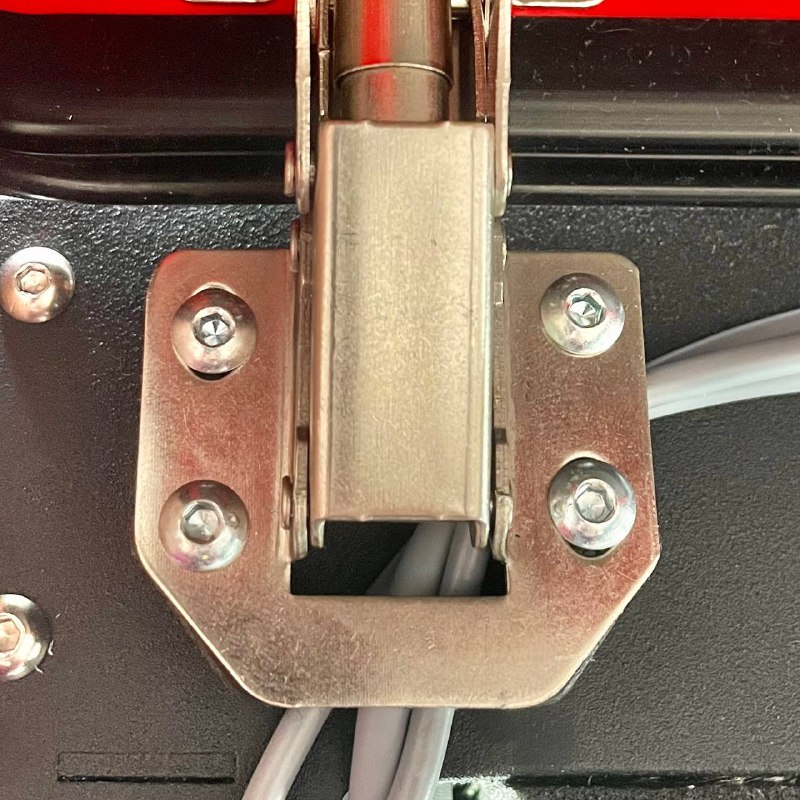
Release Hinges
- Position: Station one person ready to support the Lid's weight, while the second person accesses the hinges.
- Release Hinges: Use the 5.5 mm Wrench and the 2 mm Hex Driver to unscrew hinges from the Lid.
Detach Lid Assembly
- Support Lid: Person 1 must now securely hold and support the full weight of the Lid, keeping it stable and preventing it from dropping or twisting as it's detached.
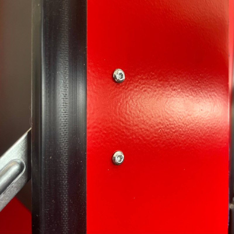
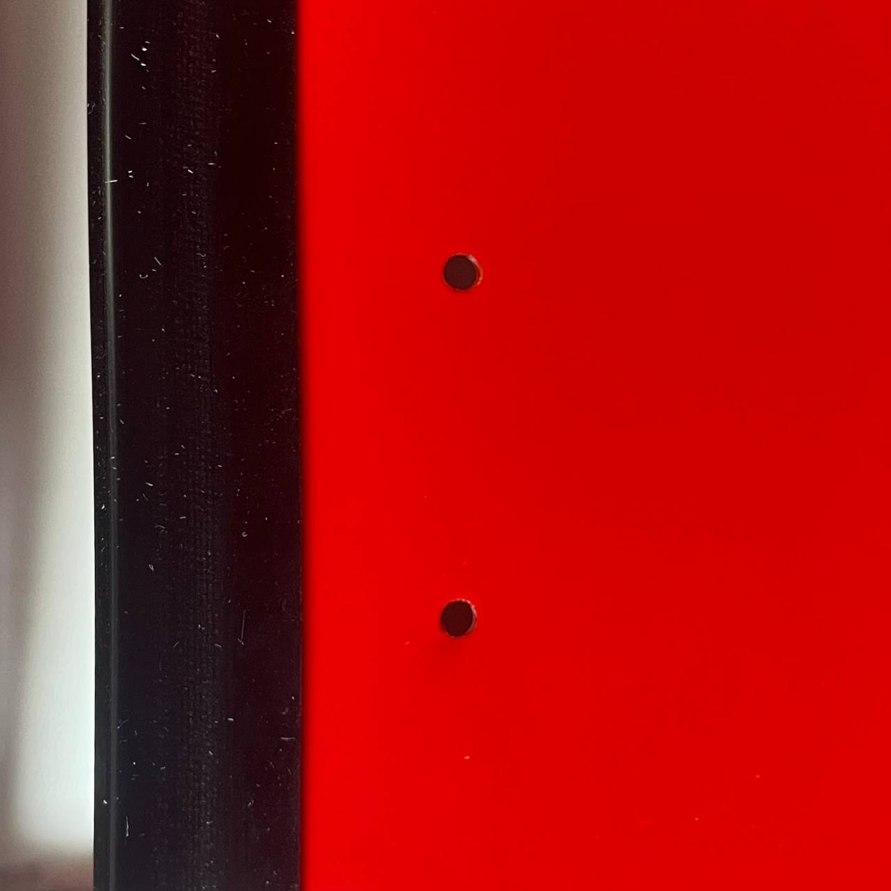
- Remove Mounting Screws: Person 2 uses the 2.5 mm Hex Driver to carefully remove all screws that fasten the Lid's mounting brackets (front and rear) to the main printer frame. Place the screws in a safe location.
- Lift Away: Working together, carefully lift the entire Lid assembly straight up and away from the printer frame. Coordinate the lift to maintain balance.
- Place Safely: Carry the Lid assembly to the prepared safe area and gently set it down, avoiding stress on any attached components.
3. Installing the Lid
Prepare Lid
- Attach the rear mounting bracket to the Lid assembly itself using the 2.5 mm Hex Driver.
Position and Secure Lid
- Lift and Position: With both people carefully lifting and supporting the Lid assembly, maneuver it back over the printer frame. Align the rear mounting brackets with the corresponding screw holes on the frame.
- Support Lid: Person 1 continues to securely support the Lid's weight in the correct position, preventing movement.
- Start Screws: Person 2 starts installing the screws through the rear mounting brackets into the frame using the 2.5 mm Hex Driver. Insert several screws loosely first to hold the position before proceeding.
Manage Cables and Front Bracket
Critical: Do not pinch cables
Before fully seating the Lid or tightening screws, carefully inspect the areas around all mounting points for any printer cables. Trapping cables during installation can cause electrical shorts, intermittent faults, or permanent damage to the printer. Double-check all cable paths are clear before final tightening.
- CRITICAL CABLE CHECK: Person 2 must carefully inspect the areas around all mounting points for any printer cables.
- Gently push any nearby cables clear of potential pinch points (where the bracket meets the frame or the Lid).
- Install Front Bracket: Position the front mounting brackets correctly. Insert and start the screws using the 2.5 mm Hex Driver.
- Tighten Screws: Once certain all cables are safely routed and the Lid/brackets are correctly aligned, proceed to tighten all mounting screws (2.5 mm Hex Driver) securely.
Re-attach Hinges
- Align Hinges: Carefully align the Lid's hinge points with the corresponding slots on the printer body.
- Secure Hinges: Use the 5.5 mm Wrench and 2 mm Hex Driver to re-secure the Lid to the hinge mechanisms.
- Test Hinges: Once secured, gently and slowly try closing and opening the Lid a small amount to ensure the hinges move smoothly and correctly.
4. Final Checks
- Verify all mounting and hinge screws are securely tightened.
- Confirm the Lid sits flush and is properly aligned with the printer body.
- Perform a final visual inspection around the edges for any inadvertently pinched cables.
- Reconnect the printer power cord and turn the printer on. Verify normal operation.
FAQ
Support
If you could not find an answer here, reach out to our support team.