Z-Probe Calibration
The Z-Probe calibration macro configures the servo angle, X pickup position, and optionally the Y pickup position and servo height for reliable probe pickup and placement. Run this procedure after replacing the servo motor, repositioning the probe dock, or if the probe fails to pick or place correctly.
The calibration has four stages:
- Servo angle and height adjustment – only needed after a servo motor replacement. Skip to Angle Calibration if the servo was not replaced.
- Angle calibration – aligns the probe holder angle with the dock station.
- X and Y position calibration – centers the toolhead over the dock.
- Overall test – runs multiple pick/place cycles to verify reliability.
You must calibrate when:
- Servo motor has been replaced
- Probe dock has been moved or reinstalled
- Probe fails to pick or place correctly
- Major hardware changes to the toolhead or X-axis
- Lost
user/folder on the SD card
You do not need to calibrate when:
- Changing nozzles
- Routine maintenance that does not affect the probe area
Before you begin - safety and risk
Read the Safety - Before You Begin article to understand the hazards involved in working on the Vision Miner 22IDEX V4 – including electrical, thermal, mechanical, and chemical risks. All procedures in this wiki are provided as recommendations only. By choosing to follow any procedure, you do so at your own risk.
Tools and Materials
- 2.5 mm hex screwdriver (hex wrench)
1. Starting the Calibration
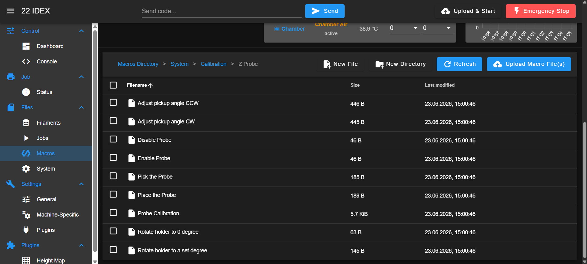
- Open the Web Interface and navigate to Macros > System > Calibration > Z Probe.
- If the probe is attached to the toolhead, detach it manually and place it in the dock at the back of the printer.
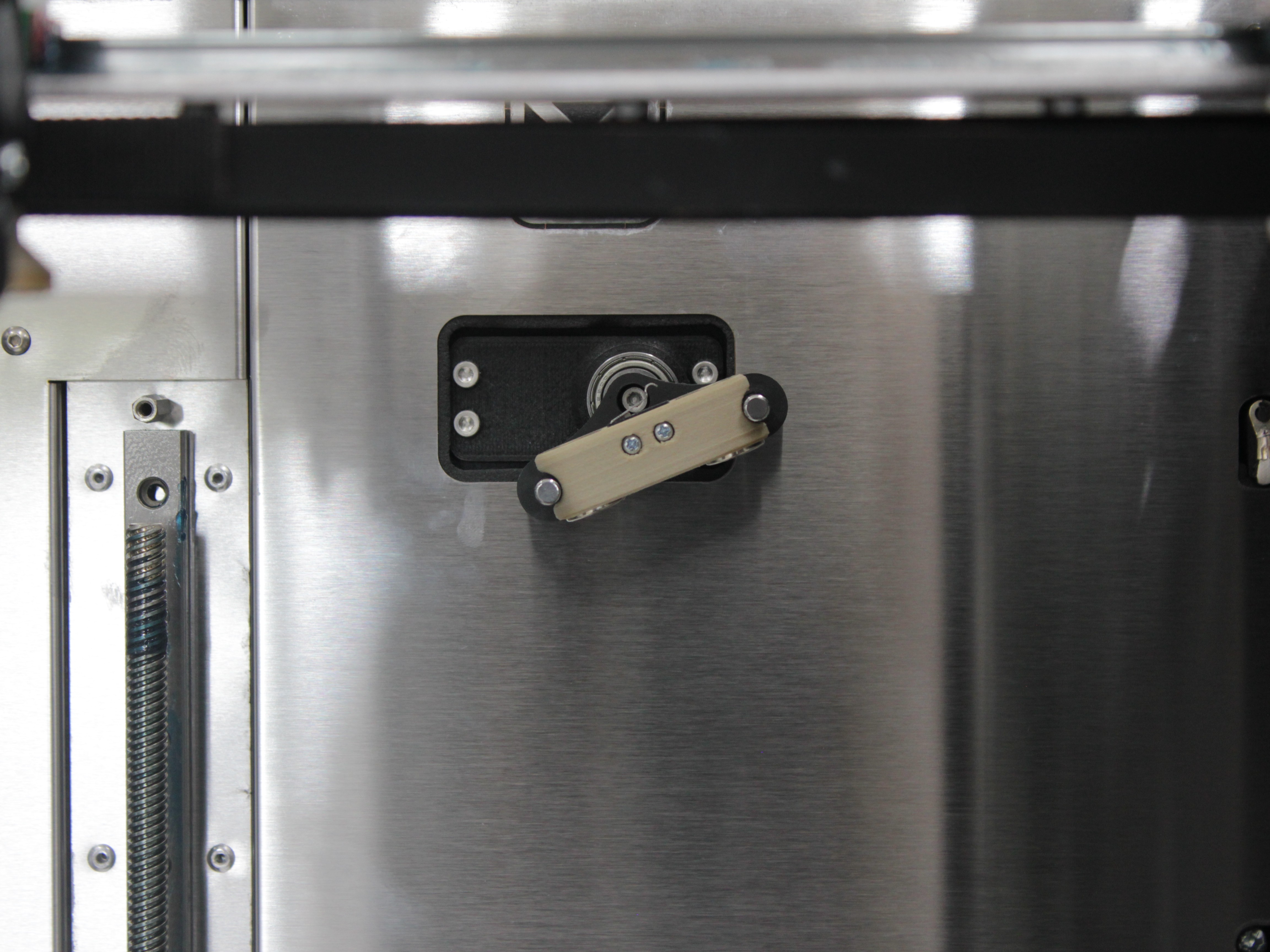
Install the probe with magnets down and lever up
The probe must sit in the dock with magnets facing down and the lever facing up. Incorrect orientation will cause calibration to fail.
- Run the Probe Calibration macro. Before homing, it checks that the probe is detached. If the probe is still attached, a "Probe Attached" dialog asks you to detach it – remove it, place it in the dock (magnets down, lever up), and press OK. If it is still detected, the macro shows "Probe Still Attached" and aborts – check the probe sensor wiring and the optocoupler PCB (see Z-Probe Troubleshooting).
- The printer then homes the Y, X, and U axes and moves to the starting position.
2. Servo Angle Adjustment
Only adjust the servo after a servo replacement
Only perform the servo angle and height adjustment if the servo motor was replaced. If the servo was not replaced, select No, Skip when prompted and continue to Angle Calibration.
The servo angle is set entirely through the macro – no screws are involved here. You only need to set it approximately: when the servo moves to its working position, the probe holder should sit roughly parallel to the horizon. This is an initial pass so the height can be adjusted next; the angle is calibrated fully later in Angle Calibration.
-
The macro asks: "Would you like to calibrate the probe pickup height?" Select Yes, Calibrate.
-
The toolhead moves near the probe dock. A dialog appears with five options:
| Option | Description |
|---|---|
Turn CCW | Rotate the probe holder counterclockwise (+1°) |
Turn CW | Rotate the probe holder clockwise (−1°) |
Test | Cycle the servo to see current alignment |
Done | Proceed when the holder appears horizontal |
Cancel | Abort calibration |
-
Press Test to see the current angle. The probe holder should appear roughly parallel to the horizon when extended.
-
Adjust with Turn CCW or Turn CW in 1° increments. Press Test after each change. When the holder is roughly parallel to the horizon, press Done.
3. Servo Height Adjustment
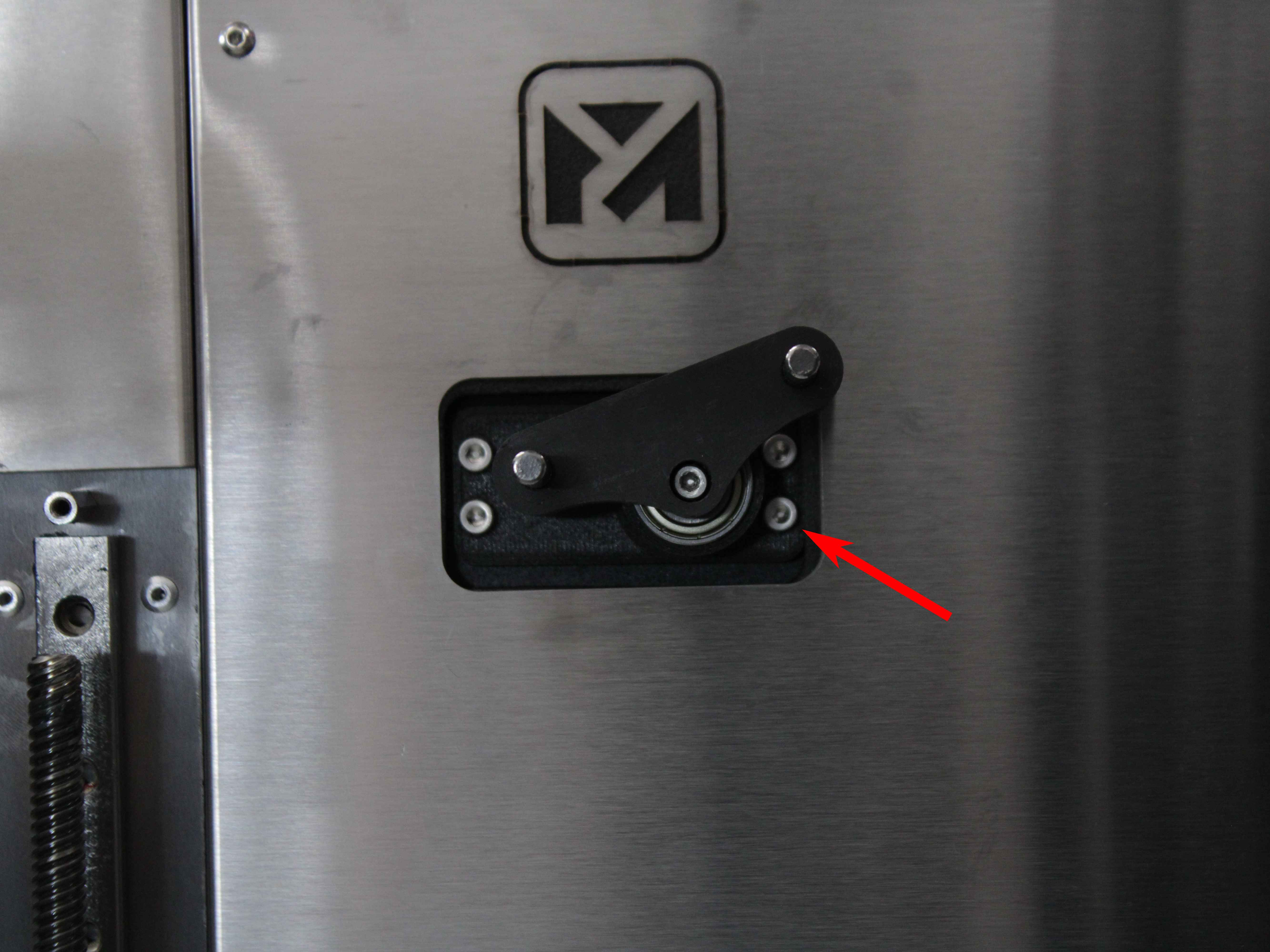
Loosening the Servo Screws
- The servo rotates to position S0. Loosen three servo screws by approximately one full turn each. Press OK.
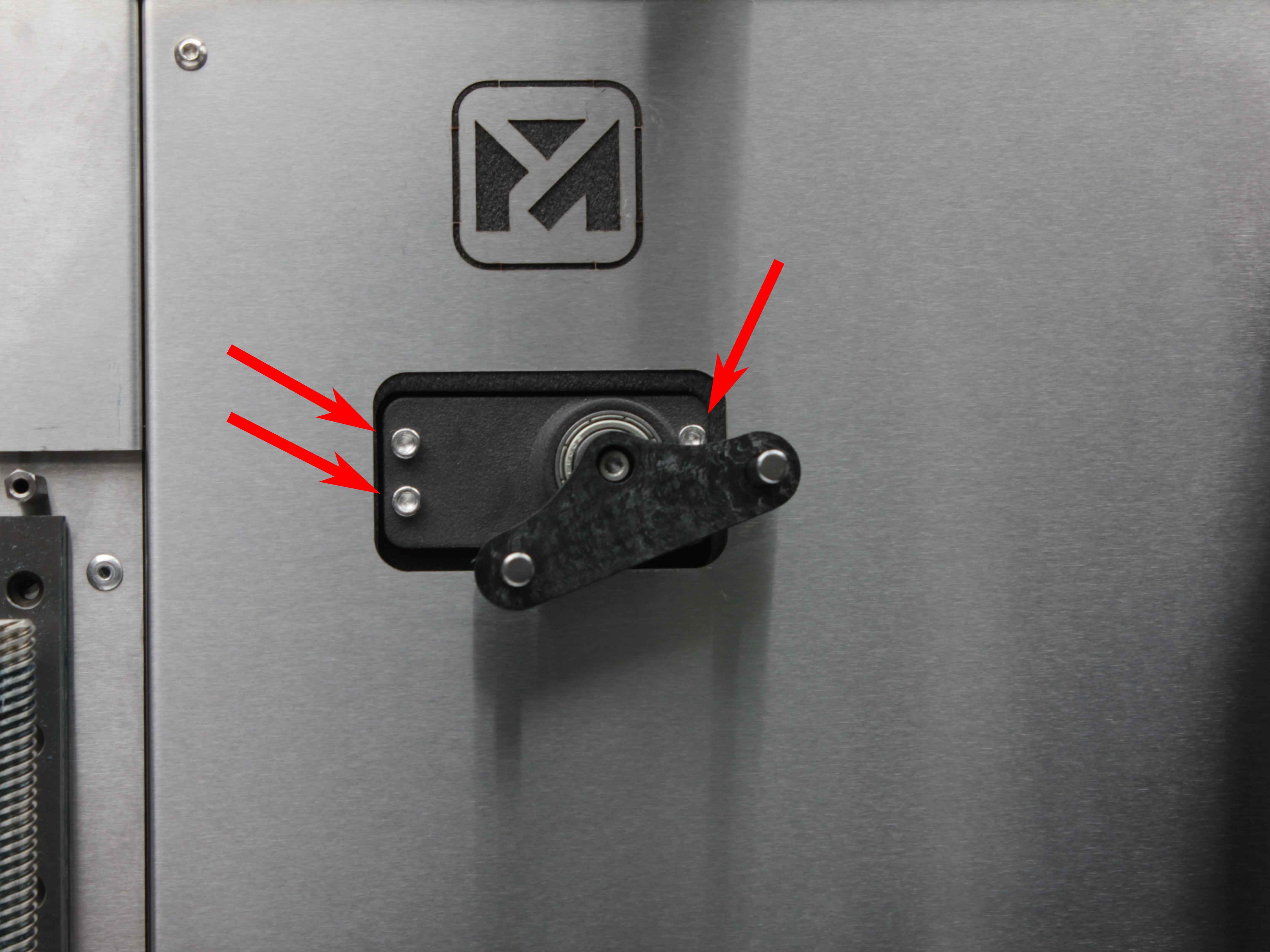
- The servo rotates to position S180. Loosen the remaining (fourth) servo screw by approximately one full turn. Press OK.
Adjusting the Height
-
The servo rotates to the saved pickup angle. Slide the servo assembly all the way down until it stops. Press OK.
-
The servo cycles through its positions (0° > set angle). Verify the probe is in the dock at the back of the printer.
Probe orientation is reversed during height adjustment
During height adjustment, the probe orientation is reversed – magnets facing up. This is only for this step. Normal operation uses magnets down, lever up.
- If the probe is not in the dock, install it manually with magnets facing up. Press OK.
Tightening the Servo Screws
- The toolhead moves to Y-max. You can jog the Y-axis for better access if needed. Press OK to save the new X position.
- Tighten at least two of the servo screws. Do not fully tighten yet. Press OK.
- The toolhead moves away (X −200 mm (≈ 7.9 in.)), then moves to Y = 0. The servo rotates to S0.
- Tighten all servo screws firmly. Press OK.
- The servo rotates to S180. Double-check that all screws are secure. Press OK.
Macro continues to angle calibration after height setup
After this step, the macro automatically proceeds to angle calibration. Do not exit.
4. Angle Calibration
The servo angle controls how the probe holder rotates toward the dock. It must match the dock angle for the probe to attach and detach cleanly. The adjustable range is 155° to 180°.
If you just completed servo height adjustment, the macro continues to this step automatically.
If starting fresh (no servo replacement): the macro reaches this step after you select No, Skip at the height calibration prompt.
- The servo cycles through its positions (0° > set angle), and the toolhead moves near the probe dock.
- A dialog appears with five options:
| Option | Description |
|---|---|
Adjust CCW | Rotate the probe holder counterclockwise (+1°) |
Adjust CW | Rotate the probe holder clockwise (−1°) |
Test | Cycle the servo to observe the current angle |
Done | Proceed when the angle is correct |
Cancel | Abort calibration |
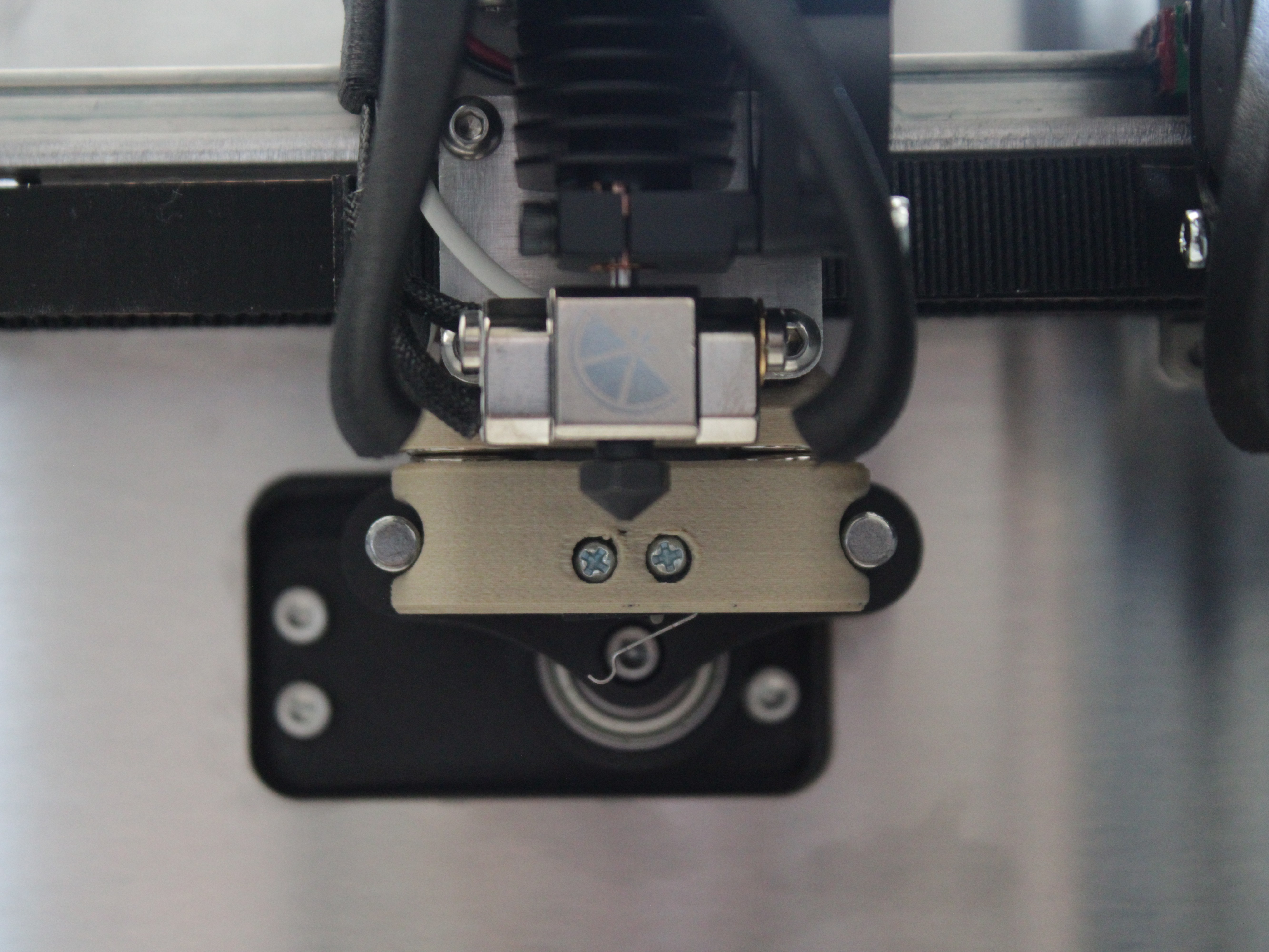
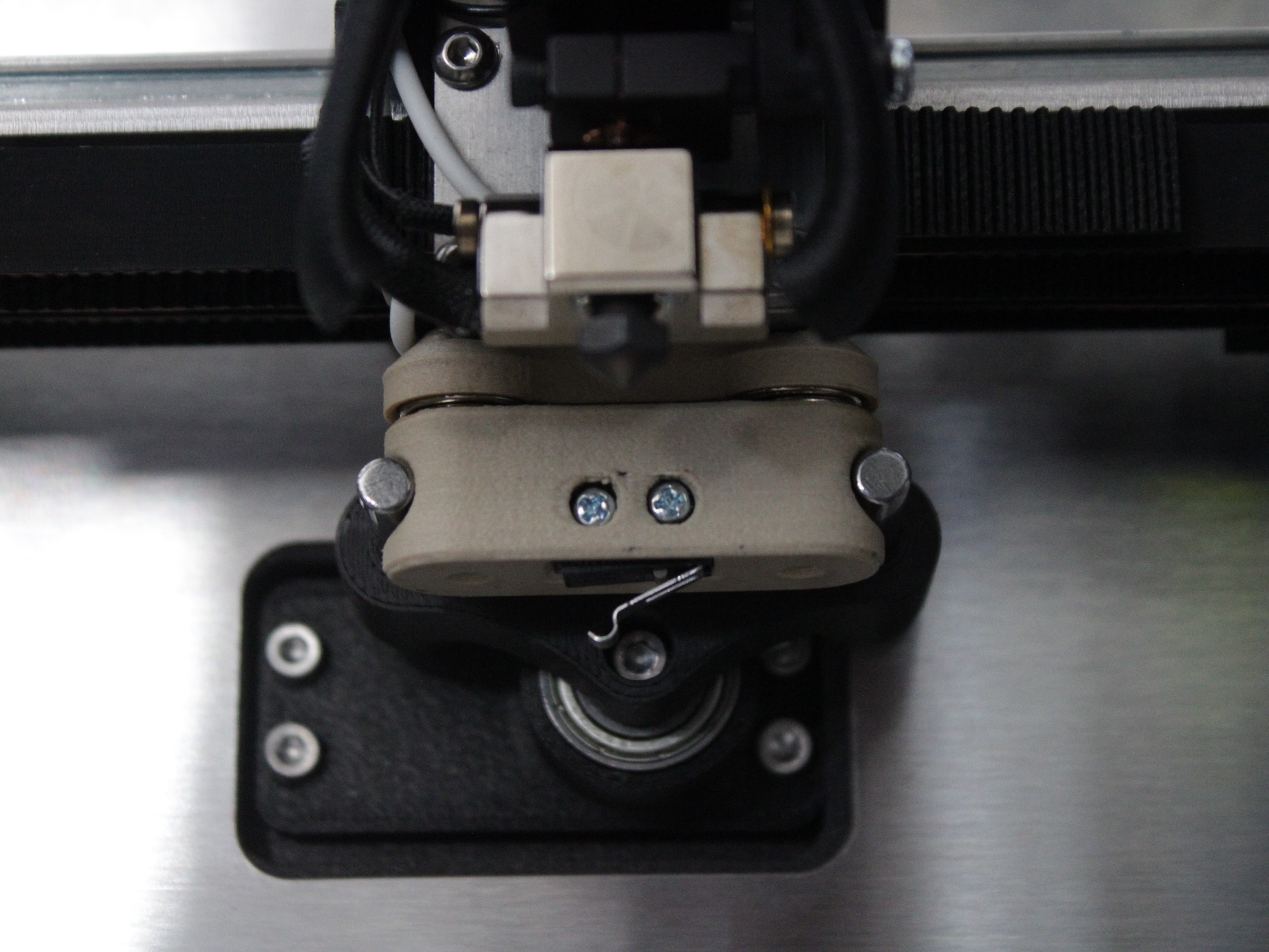
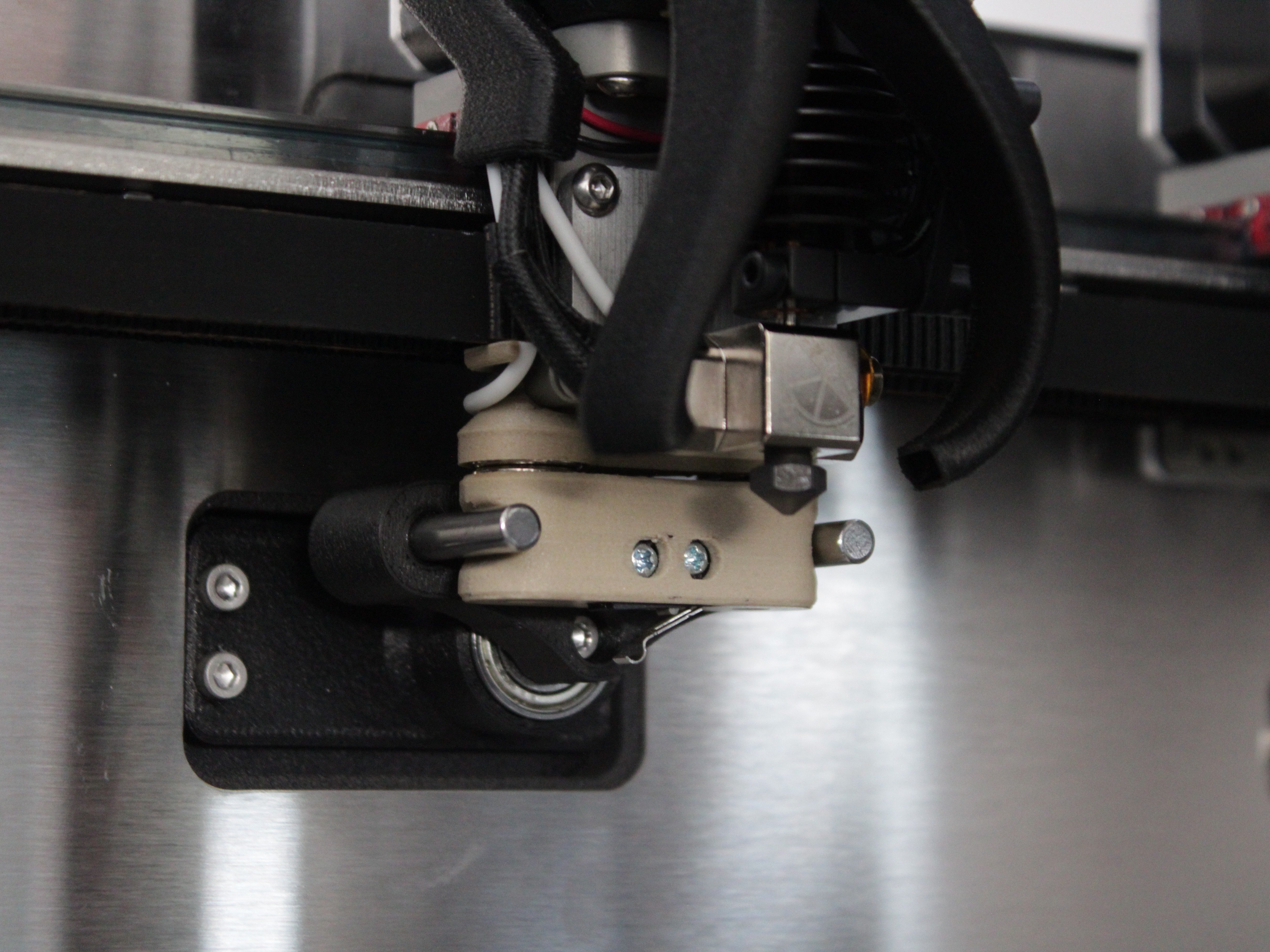
- Press Test to observe the current angle. Look at the probe holder from the side – it should be parallel to the dock when fully extended. Compare the holder angle to the dock angle at the back of the printer.
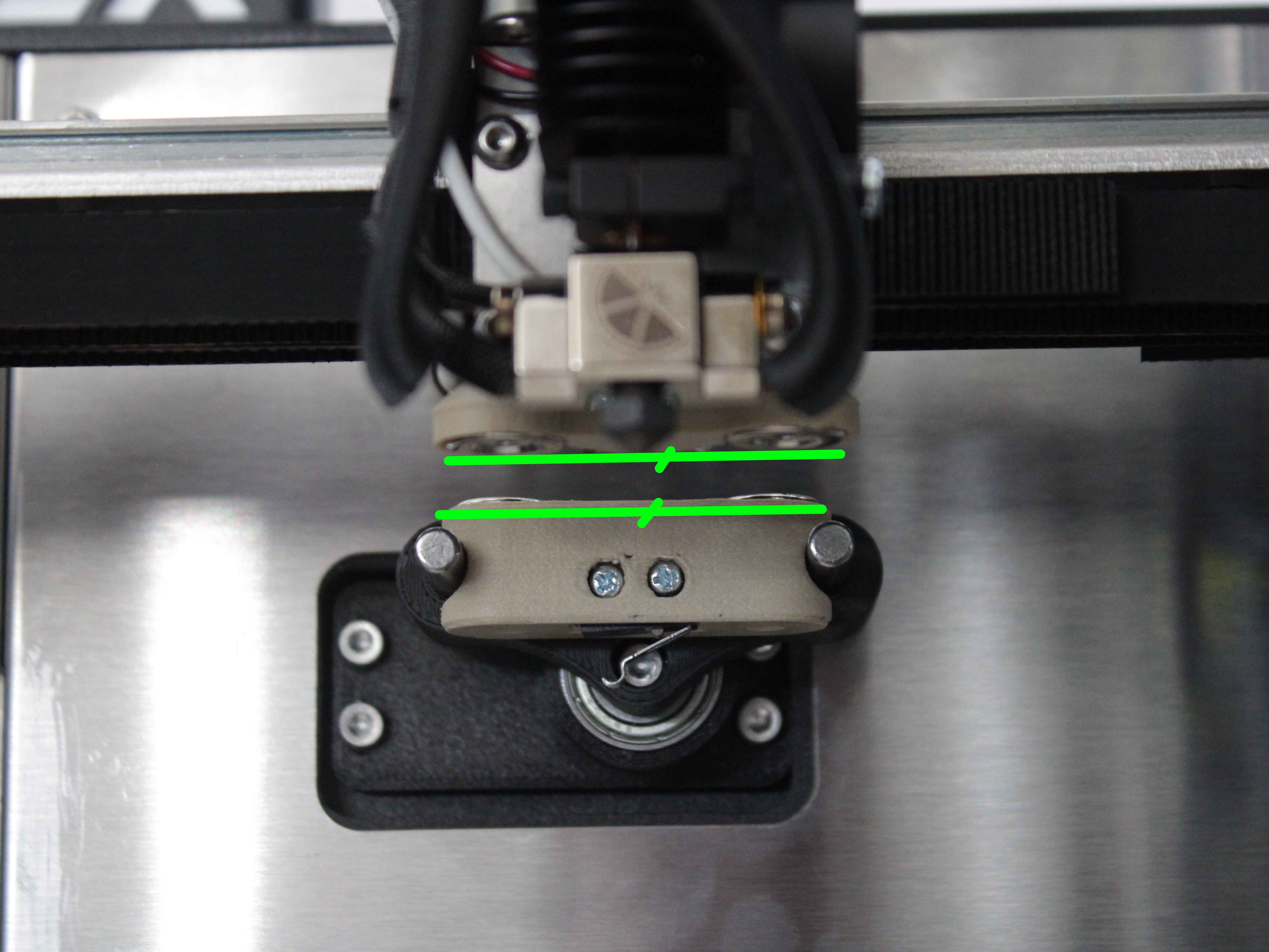
- Make small adjustments (1° at a time) using Adjust CCW or Adjust CW. Press Test after each change. When the holder angle matches the dock, press Done.
Servo angle at 155° or 180° limit
If you reach the 155° or 180° limit, the macro displays a warning. The servo may need to be physically repositioned – re-run the height adjustment (step 5) or contact support.
5. X Position Calibration
The X position determines where the toolhead stops horizontally over the dock.
- After angle calibration, the toolhead moves to the current saved pickup position. A dialog appears with X and Y jogging enabled.
- Look at the probe holder from the front. Jog the X-axis until the holder is centered over the dock – equal gap visible on both sides.
- Press OK to save the new X position.
6. Y Position Calibration (Optional)
The Y position determines how far back the toolhead travels to reach the dock.
- The macro asks: "Do you want to save Y position?"
- Yes, Save Y – saves the current Y position. Use this only if the probe is not making full contact or is being pushed too far into the dock.
- No, do not Save Y – keeps the default Y position (Y-max). Recommended for most machines.
Do not change Y if default pickup already works
If probe pickup already works at the default distance, do not change Y. Unnecessary changes can cause pickup failures.
- If you selected Yes, Save Y, you can jog the Y-axis before confirming to fine-tune how far back the toolhead travels. Open the printer lid and look down at the probe holder and dock from above to check contact depth.
7. Overall Test
- The macro runs an automatic test sequence:
- Places the probe (if currently attached)
- Picks the probe – three consecutive attempts
- Places the probe
- Watch each cycle. The probe should attach cleanly during pickup and detach cleanly during placement – no scraping, bumping, or missed connections.
- The macro asks: "Was the probe picked and placed correctly?"
- Yes – calibration is complete. The macro displays "Probe calibration successful."
- No – the macro displays "Please repeat the procedure." Run the calibration again, focusing on whichever step looked off:
- Probe scrapes or misses magnets – adjust angle (step 20)
- Probe off-center – recenter X position (step 24)
- Probe does not contact dock – check Y position (step 26)
FAQ
Troubleshooting
Support
If you could not find an answer here, reach out to our support team.