Build Plate Securing Screws
The Vision Miner 22IDEX V4 uses three build plate securing screws that pass through the build plate and thread into the build plate holders, secured from the bottom with a nut. This article explains what these screws do, where they are, and how to check them after receiving the printer.
Before you begin - safety and risk
Read the Safety - Before You Begin article to understand the hazards involved in working on the Vision Miner 22IDEX V4 - including electrical, thermal, mechanical, and chemical risks. All procedures in this wiki are provided as recommendations only. By choosing to follow any procedure, you do so at your own risk.
How the Bed Mount Works
The build plate sits on three support points arranged in a triangle – two at the front (left and right corners) and one at the rear (center). At each point, a steel ball is attached to the underside of the bed. Each ball rests in a holder with two guide rails, allowing the ball to slide along a fixed path.
This is a kinematic coupling – the bed is not rigidly attached to the holders. Because the bed heats to very high temperatures, it must be free to expand in all directions. If the bed were clamped down tightly, thermal expansion would cause it to warp or bow. By allowing free movement, the bed stays flat across its entire surface at any temperature.
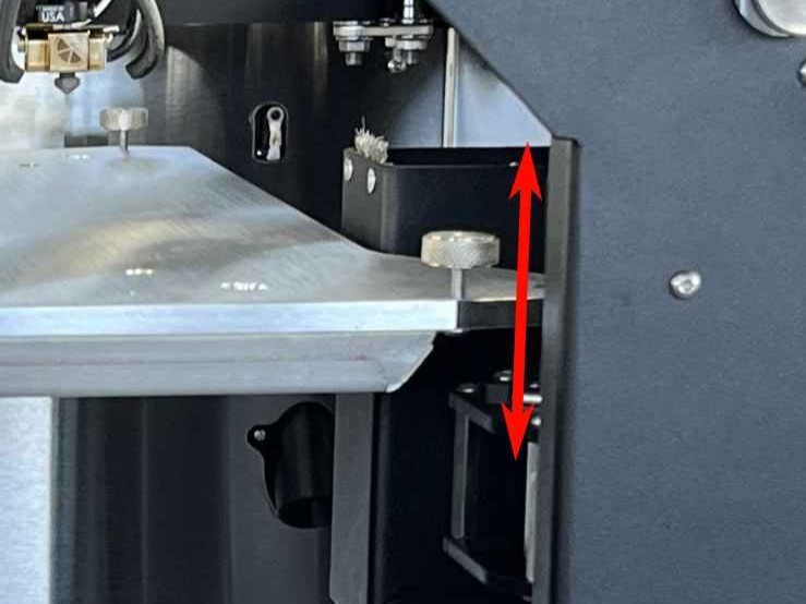
Each build plate securing screw passes through a hole in the build plate, threads into the build plate holder, and is secured from the bottom with a nut. The screws prevent the build plate from falling off the holders, but they must not clamp the build plate down. The build plate should have 2–3 mm of upward play at each of the three screw locations. This play is essential – it lets the build plate expand freely when heated and tilt during automatic bed leveling.
The screws can be removed entirely, but this is not recommended during normal operation – if an emergency occurs (e.g. a crash or sudden stop), the bed could fall off the holders.
Screw Locations and Specifications
Three countersunk M3 screws, one at each bed support point:
- Front left – left corner of the bed frame
- Front right – right corner of the bed frame
- Rear center – center rear of the bed frame
Tools needed (only if adjustment is required):
- 2 mm Hex screwdriver (hex wrench)
- 5.5 mm wrench or socket
Checking the Bed After Receiving the Printer
The screws are pre-configured at the factory. After receiving the printer, verify that the bed has 2–3 mm of upward play in all three corners:
- Gently lift the bed upward at each of the three screw locations (front left, front right, rear center).
- The bed should move up freely by 2–3 mm at each point.
- If the bed moves freely upward at all three corners – the screws are set correctly and the printer is ready for use.
If the bed is locked and has no upward play, use a 2 mm hex screwdriver to hold the screw and a 5.5 mm wrench to loosen the nut from the bottom. Unscrew the screw a few millimeters upward until the bed has 2–3 mm of play, then re-tighten the nut to lock the screw in this new position.
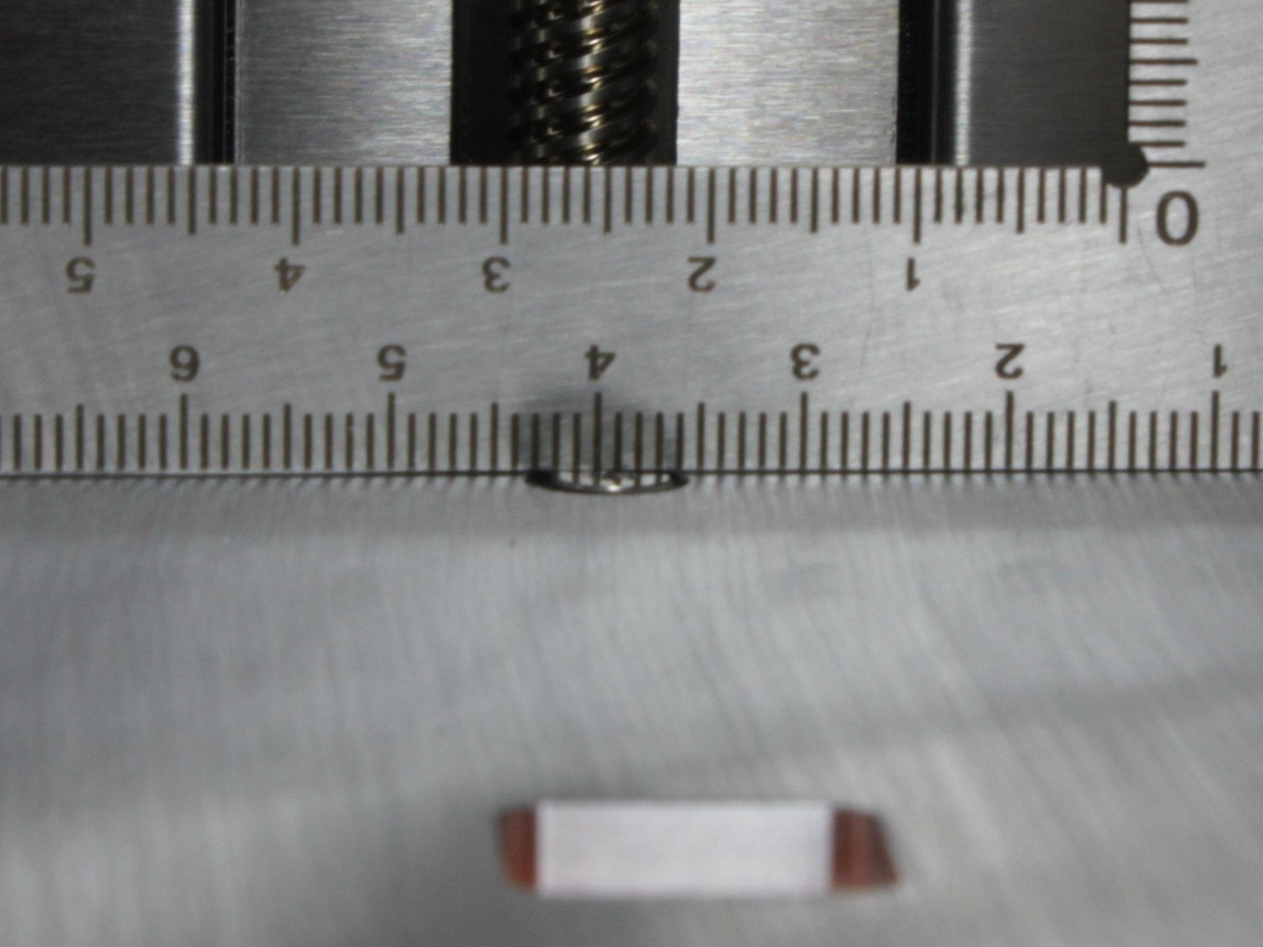
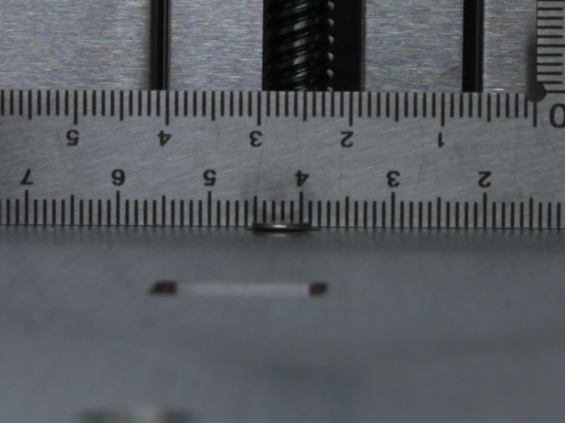
Rear Screw – Must Be Flush with the Bed Surface
The rear center screw must not protrude above the bed surface. If it sticks up, it will push against the build plate from below and distort the bed mesh height map, causing uneven first layers.
After checking play, verify that the rear screw head is flush with or slightly below the bed surface. If it protrudes, it can push the build plate up from below and make the surface uneven. Use a 2 mm hex screwdriver to turn it down until it is flush.
To check, slide a credit card (or similar thin, flat object) between the bed surface and the build plate at the rear screw location. If the card catches on the screw head, the screw is protruding and must be turned down. You can also place the build plate on the bed and feel for any wobble at the rear – if the plate rocks, the rear screw is likely too high.
Transport
Before transporting the printer, verify that all three build plate securing screws are present and have the standard 2–3 mm of upward play. The screws keep the build plate attached to the holders during transit. Do not tighten them beyond the normal setting.
Make sure all three build plate securing screws are installed before shipping or relocating the printer. Do not overtighten them.
After arriving at the new location, check the bed play again as described above.
FAQ
Support
If you could not find an answer here, reach out to our support team.