24V PSU Replacement
This guide covers replacing the 24V power supply unit (PSU) on the Vision Miner 22IDEX V4. You may need this procedure if the PSU has failed, is producing inconsistent voltage, or has been damaged.
Before you begin - safety and risk
Read the Safety - Before You Begin article to understand the hazards involved in working on the Vision Miner 22IDEX V4 – including electrical, thermal, mechanical, and chemical risks. All procedures in this wiki are provided as recommendations only. By choosing to follow any procedure, you do so at your own risk.
High voltage hazard inside the electronics bay
This procedure involves the high-voltage section of the printer's electronics. The PSU converts mains AC voltage (110–240 V) to 24 V DC. Even after powering off, dangerous voltages may be present inside and on the terminals of the PSU. Only qualified personnel should perform this replacement.
Tools and Materials
- 2.5mm HEX - Wera Screw Driver (hex wrench)
- PH2 Phillips screwdriver (for PSU terminal screws)
- Threadlocker (we recommend Loctite 243)
- 24V Power Supply Unit
Power Off and Preparation
1. Turn off the printer using the power button.
2. Unplug the mains power cable from the back of the printer.
Wait 60 seconds for PSU capacitors to discharge
Wait at least 60 seconds after unplugging for the capacitors inside the PSU to discharge. Do not touch any terminals or wiring until this time has passed.
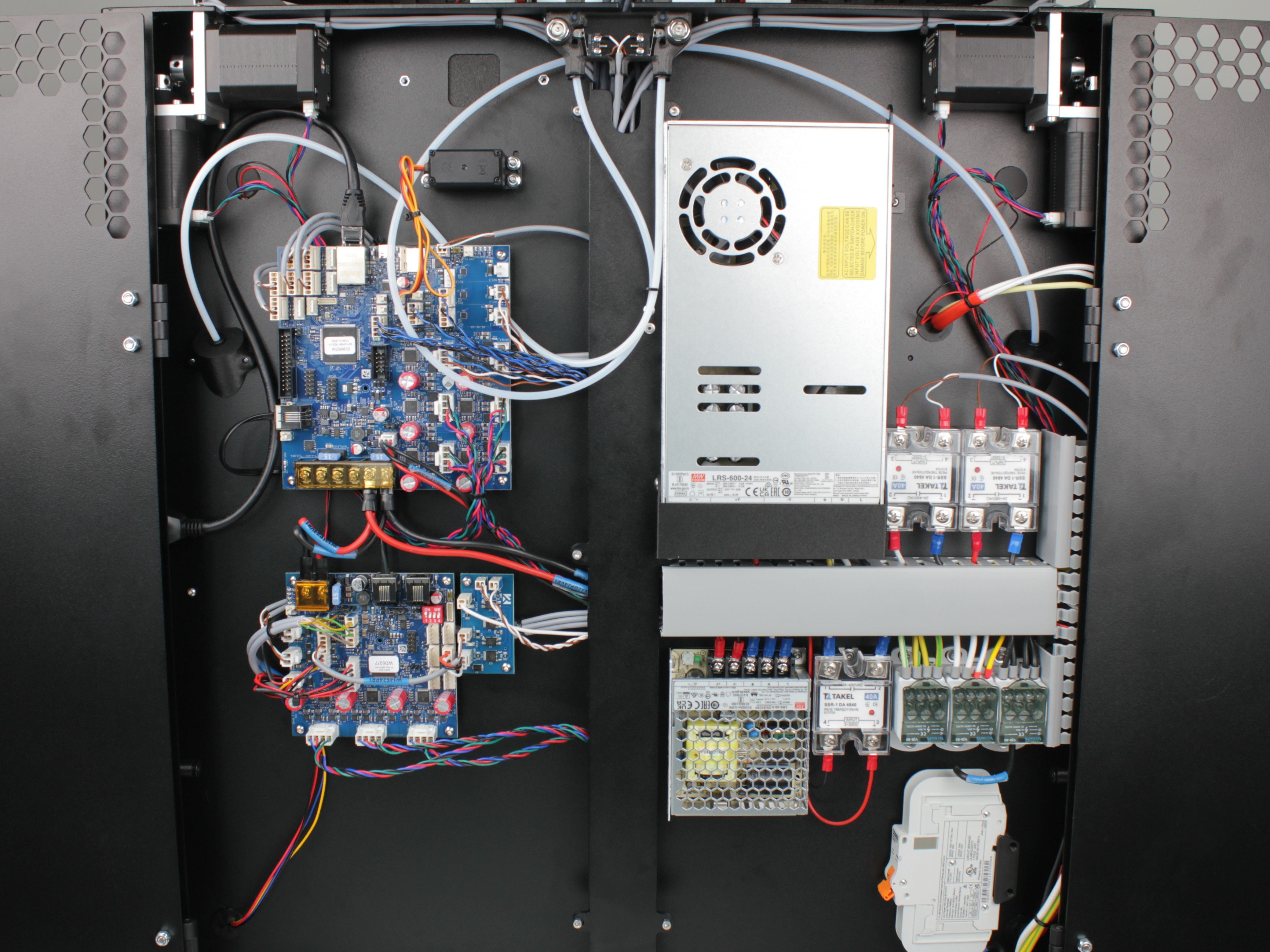
3. Open the rear electronics bay to access the PSU.
Removing the Terminal Protective Cover
4. Unscrew the two 2.5 mm hex screws holding the 3D-printed protective cover over the PSU terminals.
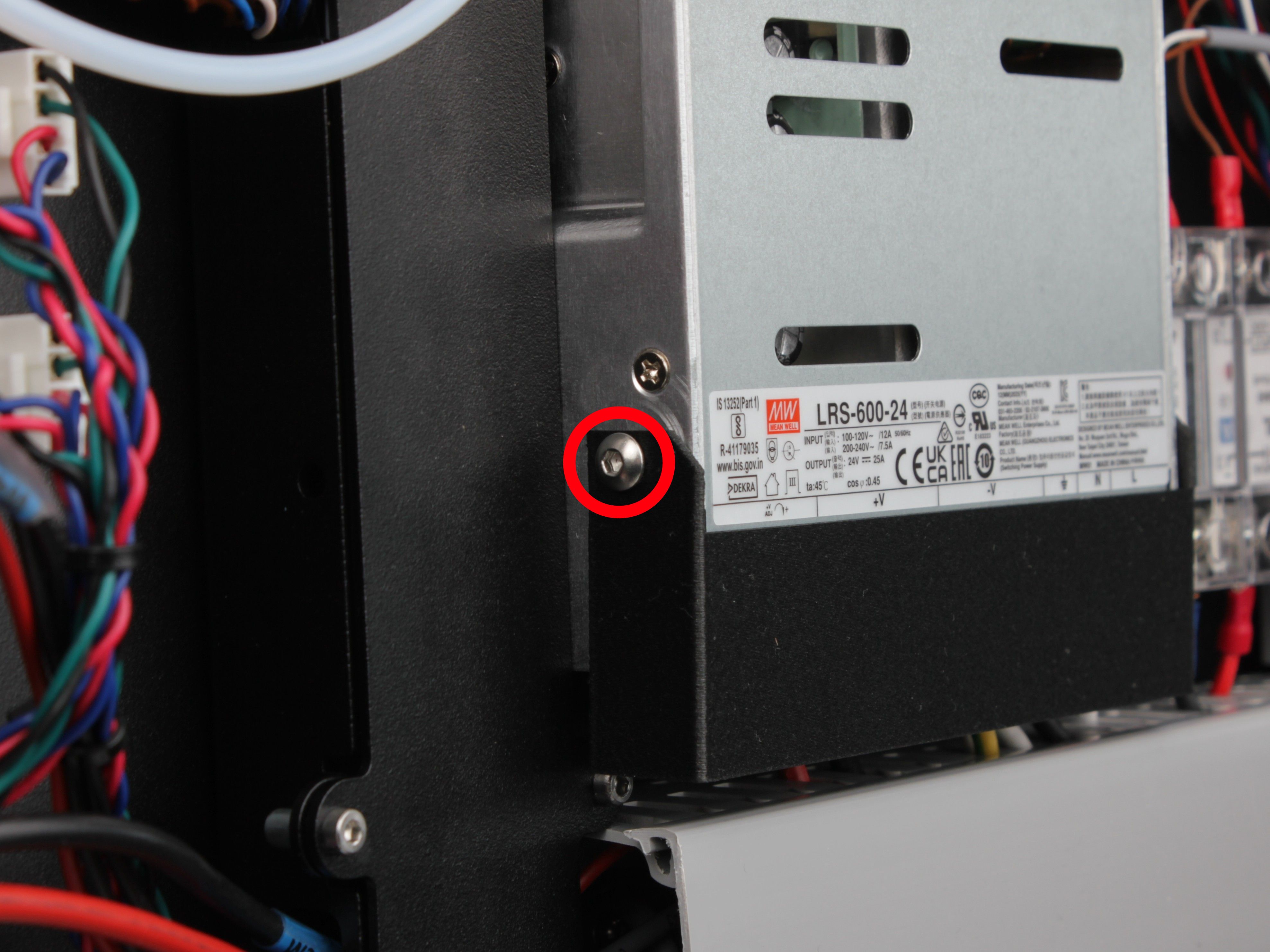
Hex screw on the first side of the terminal cover
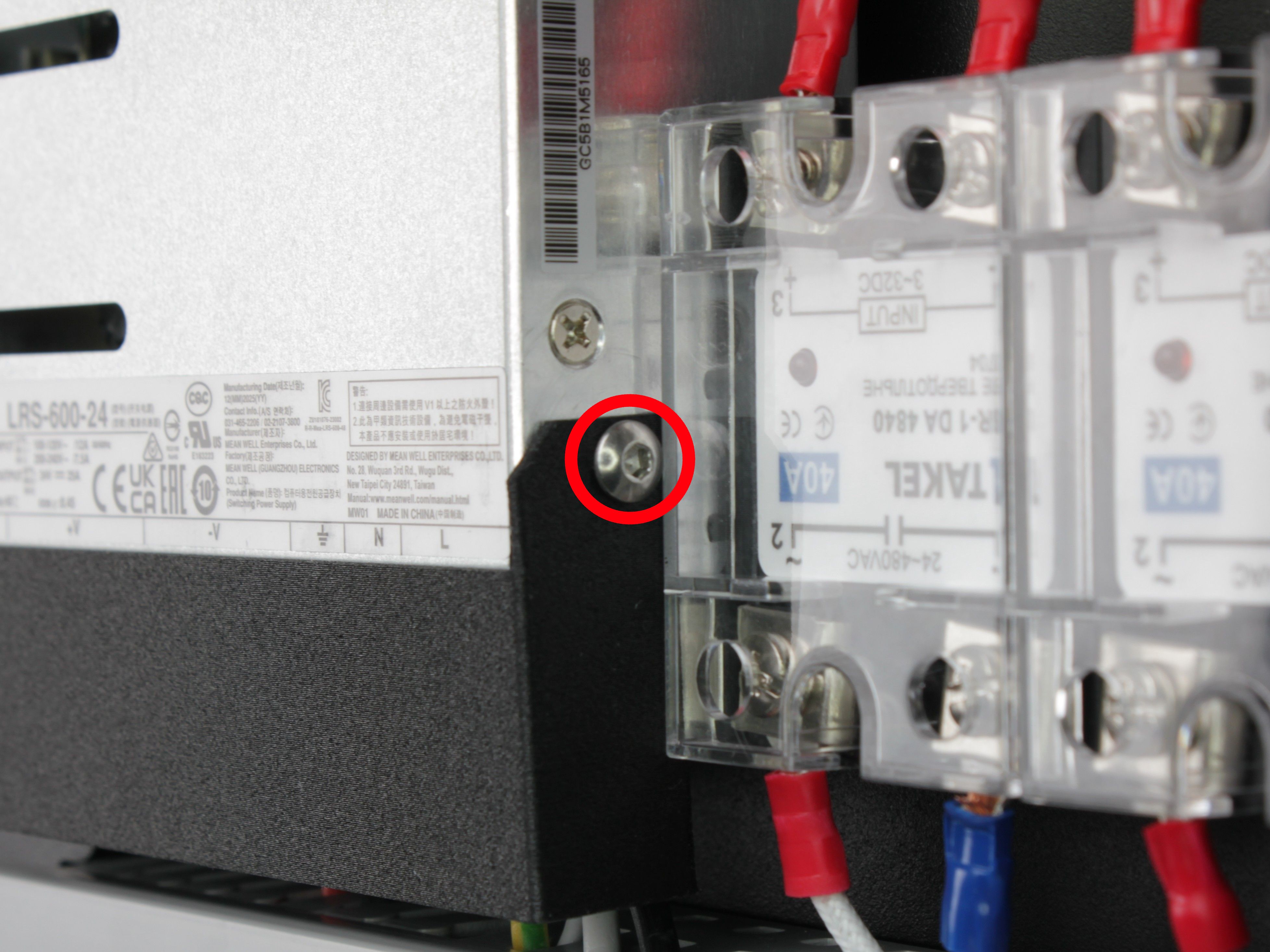
Hex screw on the other side of the terminal cover
5. Remove the protective terminal cover and set it aside.
The terminals and wire colors are now visible.
Documenting Terminal Wiring
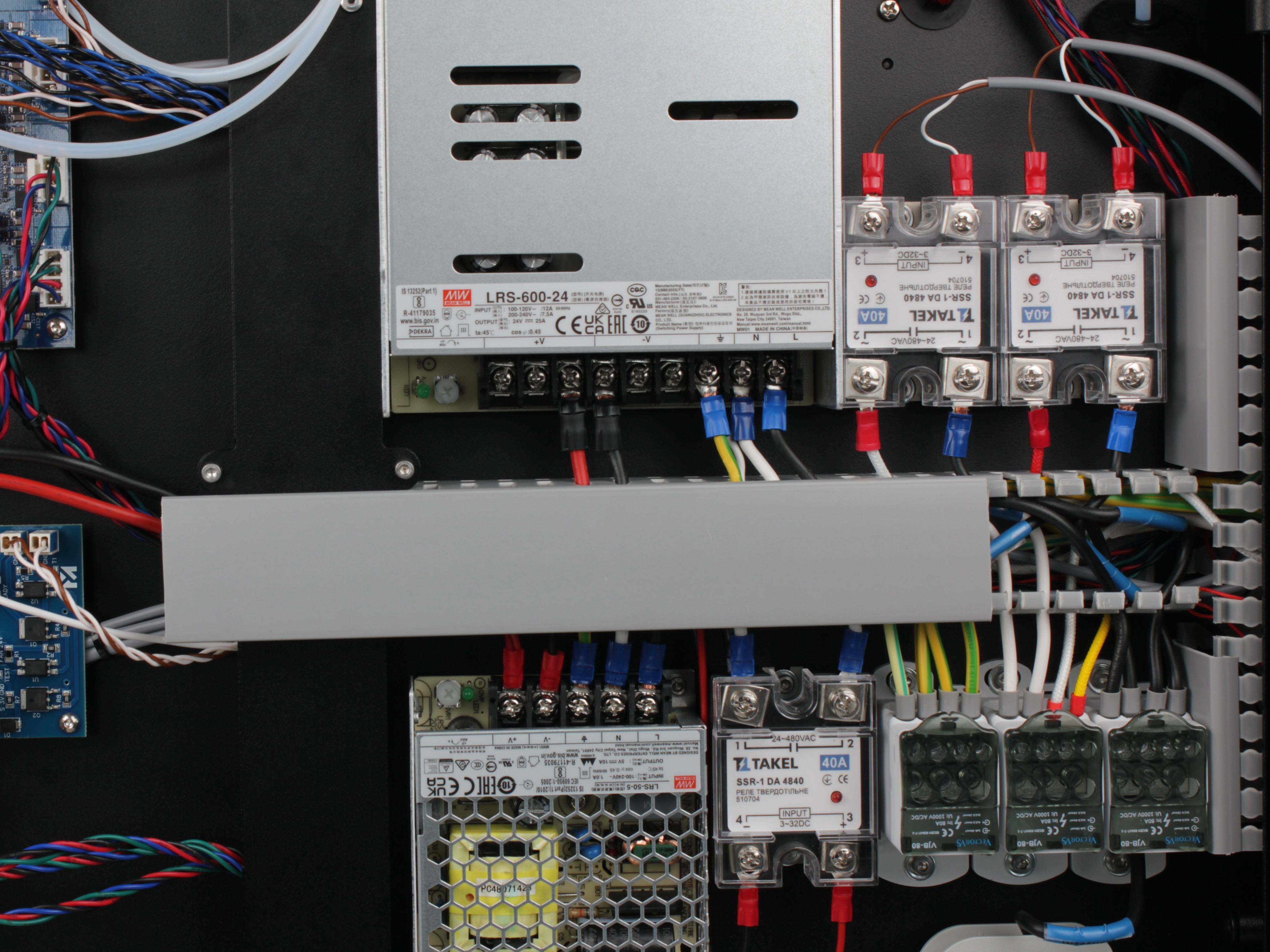
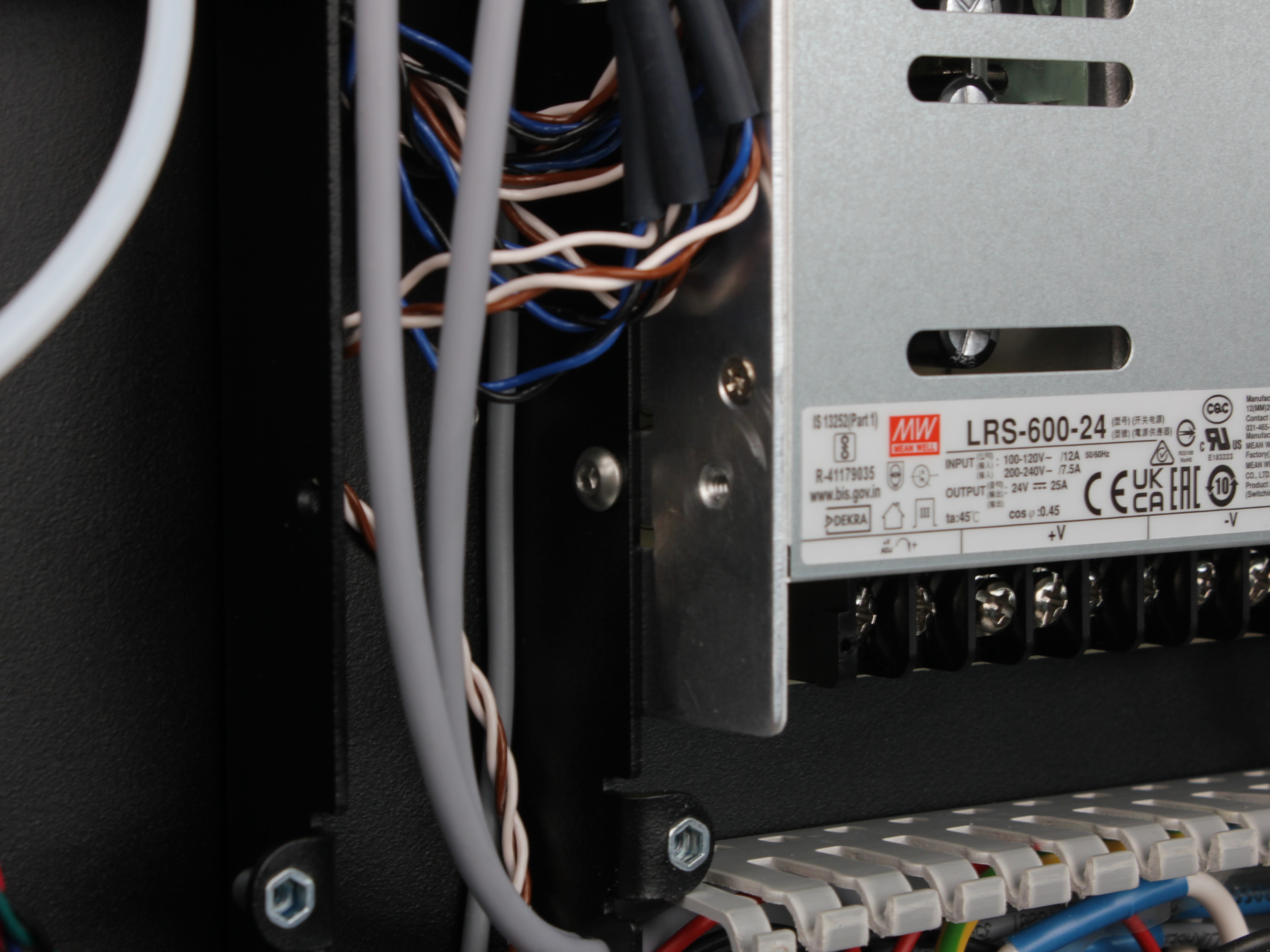
Photograph all PSU terminals before disconnecting anything
Before disconnecting any wires, photograph all terminal connections on the PSU. Capture which wire goes to which terminal, in which order. You will need this reference during reassembly.
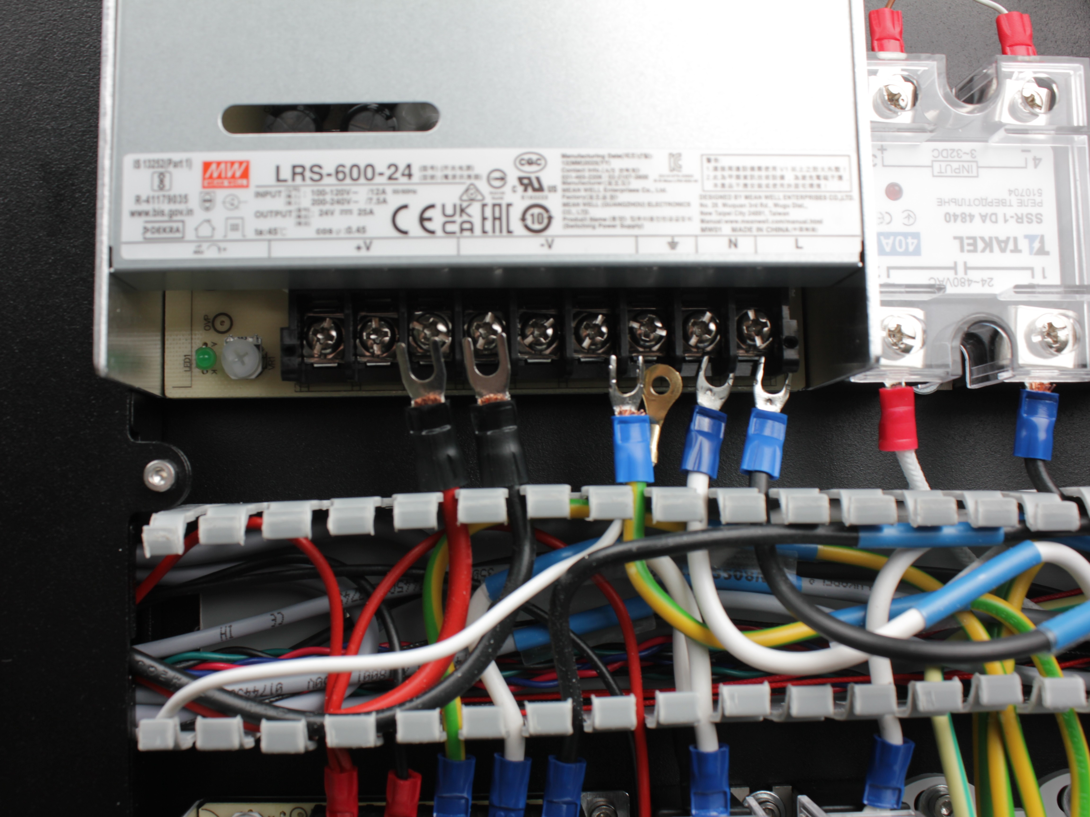
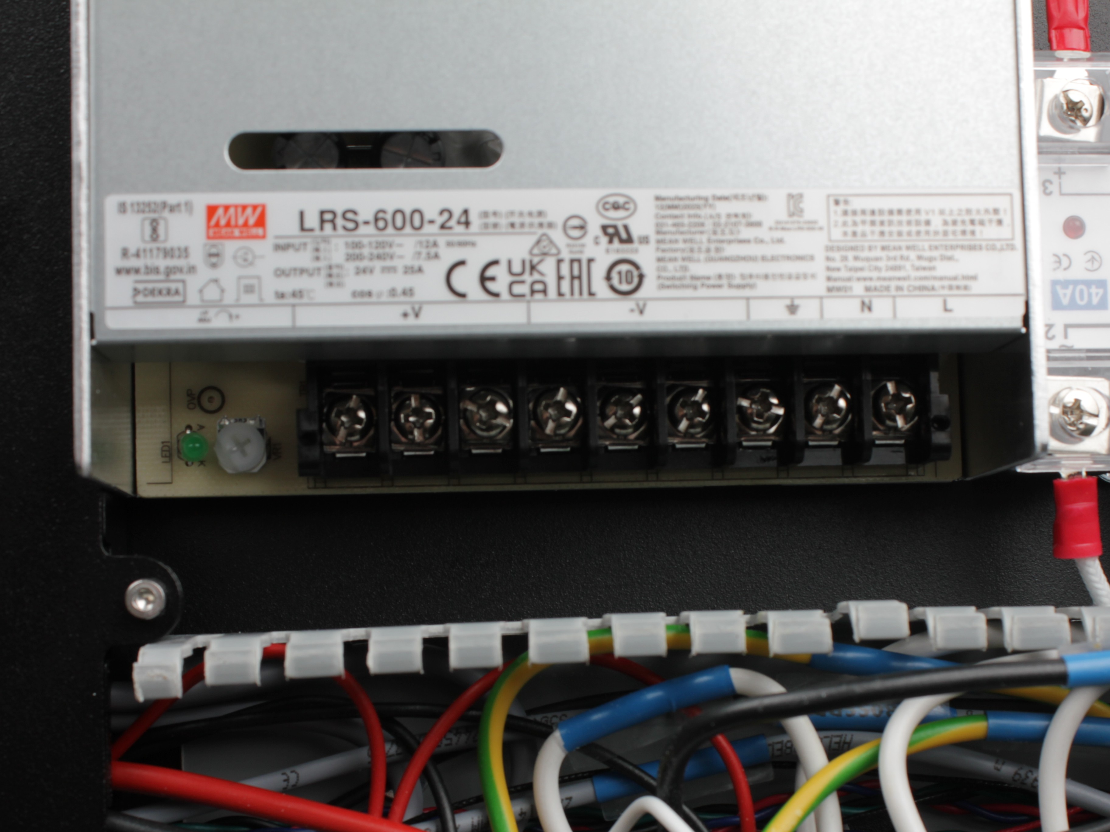
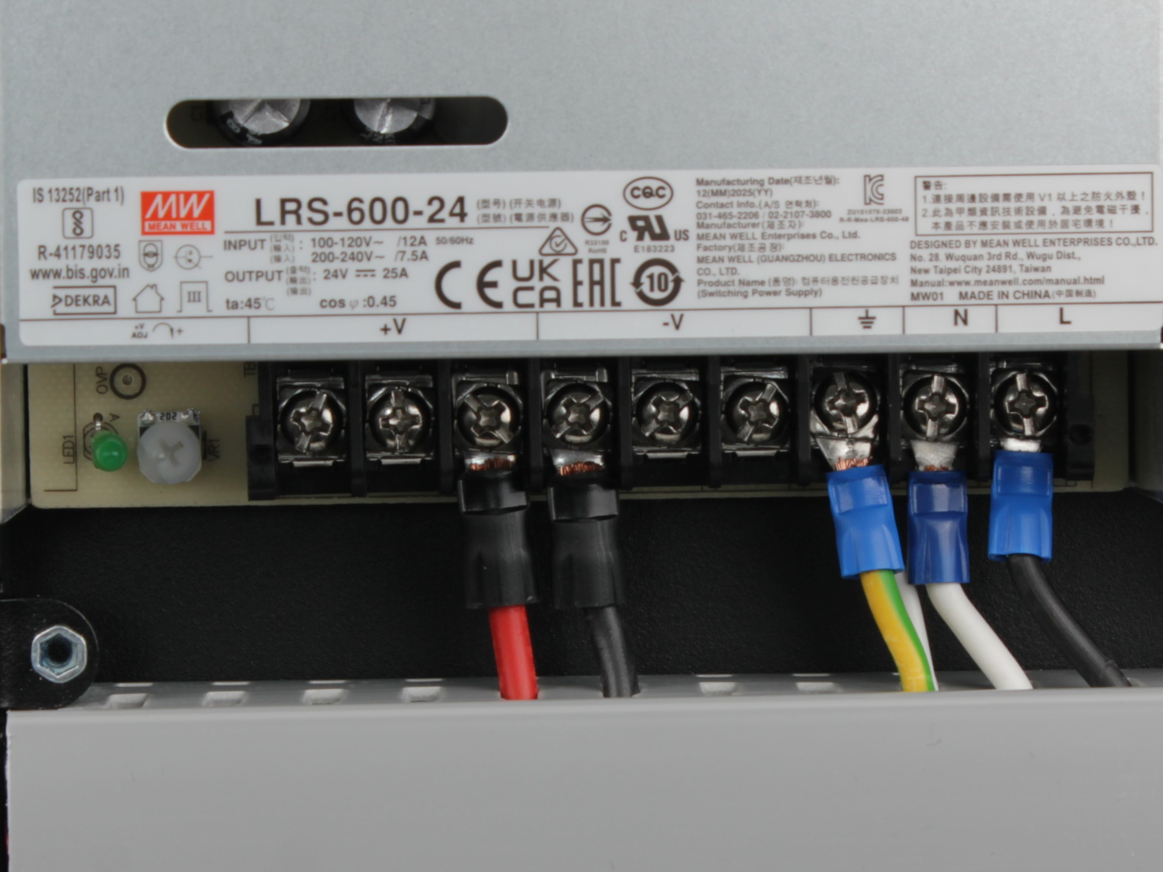
6. Photograph the PSU terminals from multiple angles.
Capture the wire positions, colors, and terminal labels clearly.
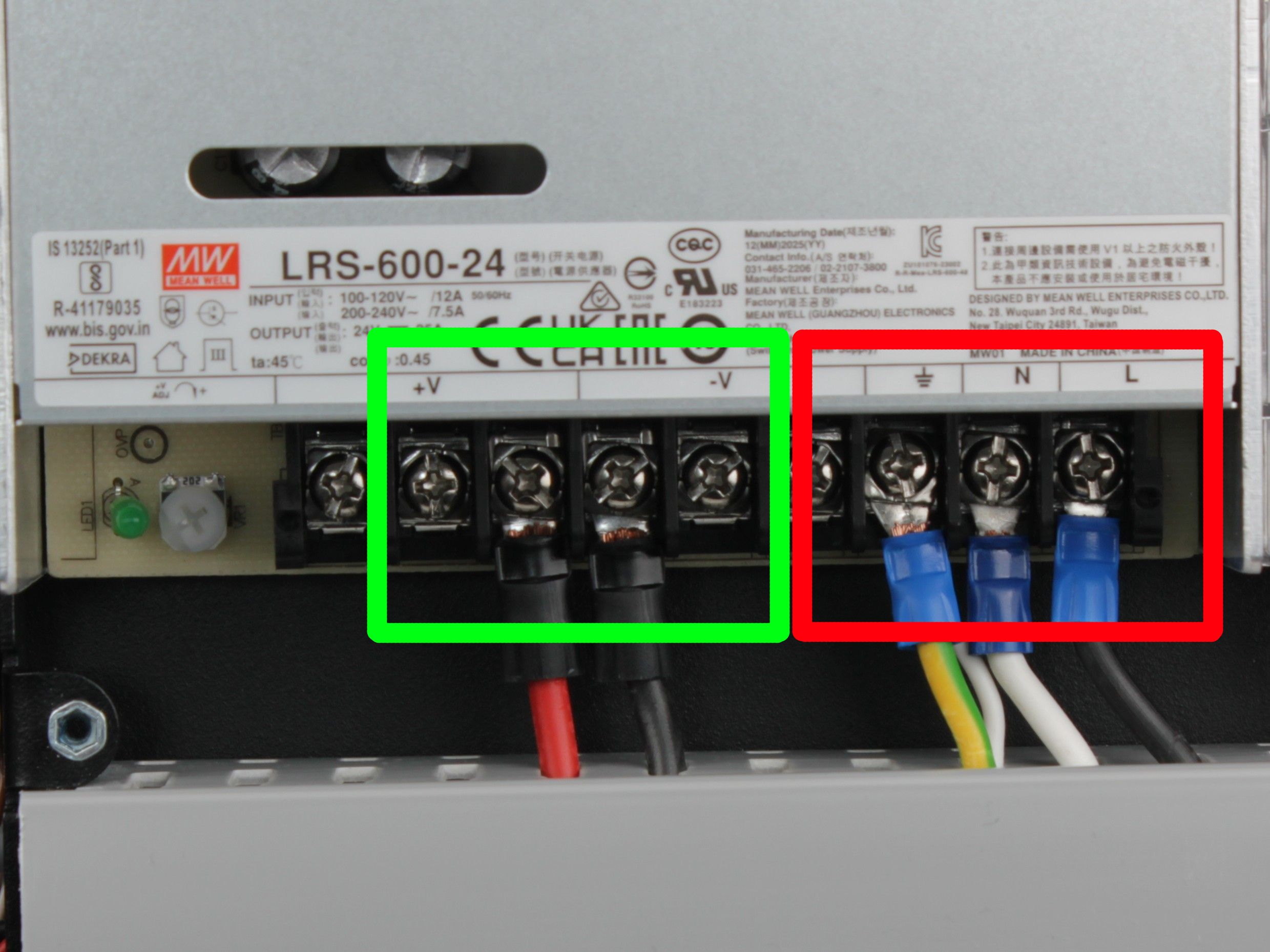
Red – high-voltage side (mains AC input). Green – low-voltage side (24V DC output).
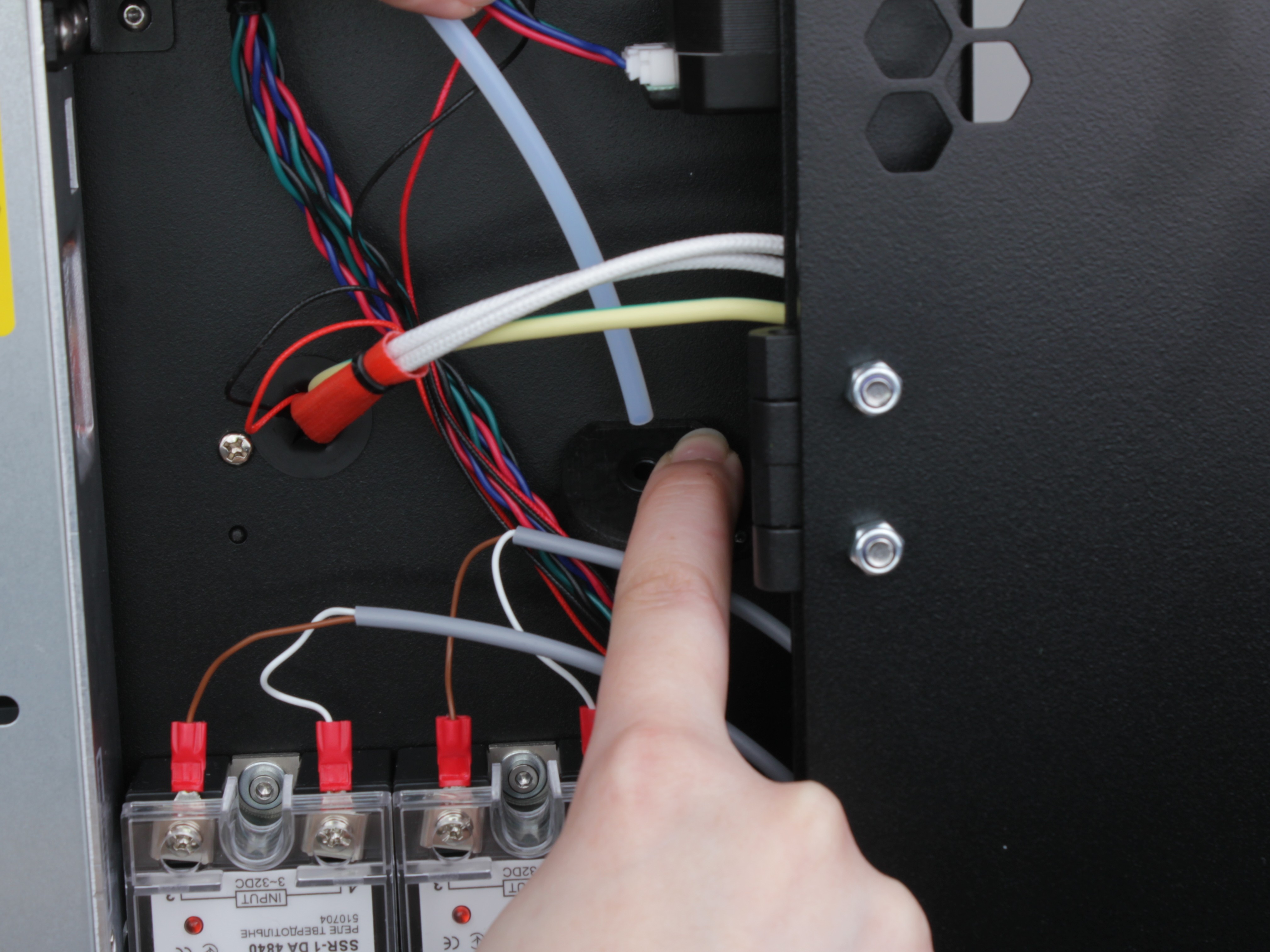
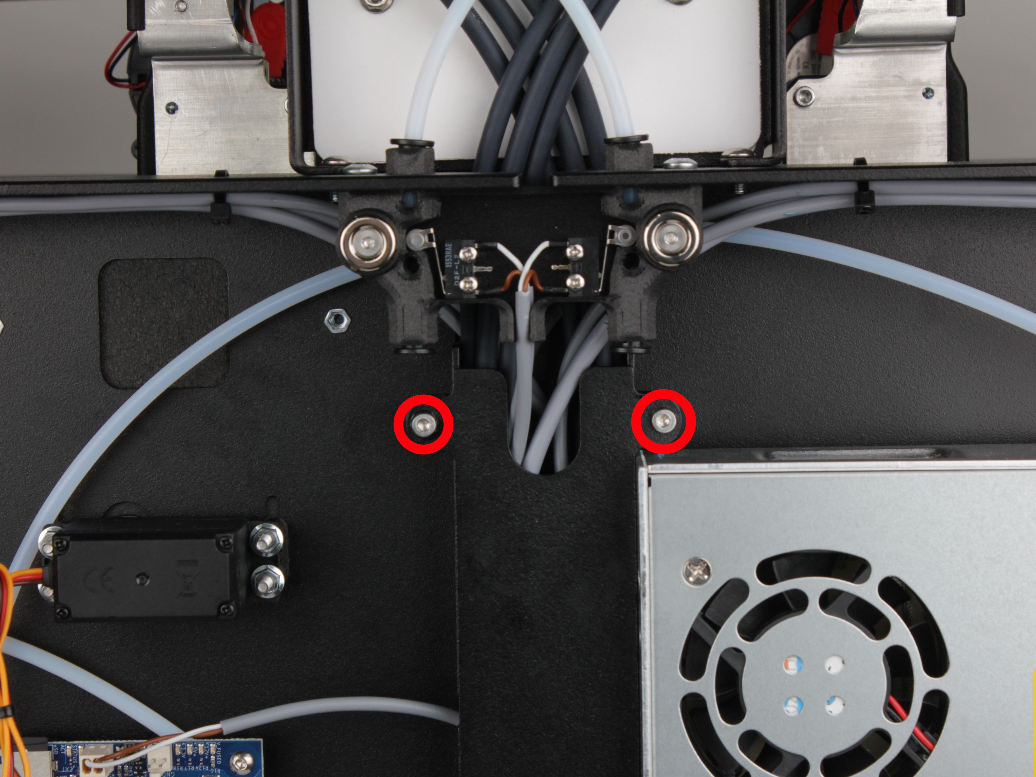
Removing the Cable Channel Cover
7. Remove the cable channel cover (wire duct lid) located underneath the PSU.
This exposes the wiring below.
Pulling the cable channel cover to the side
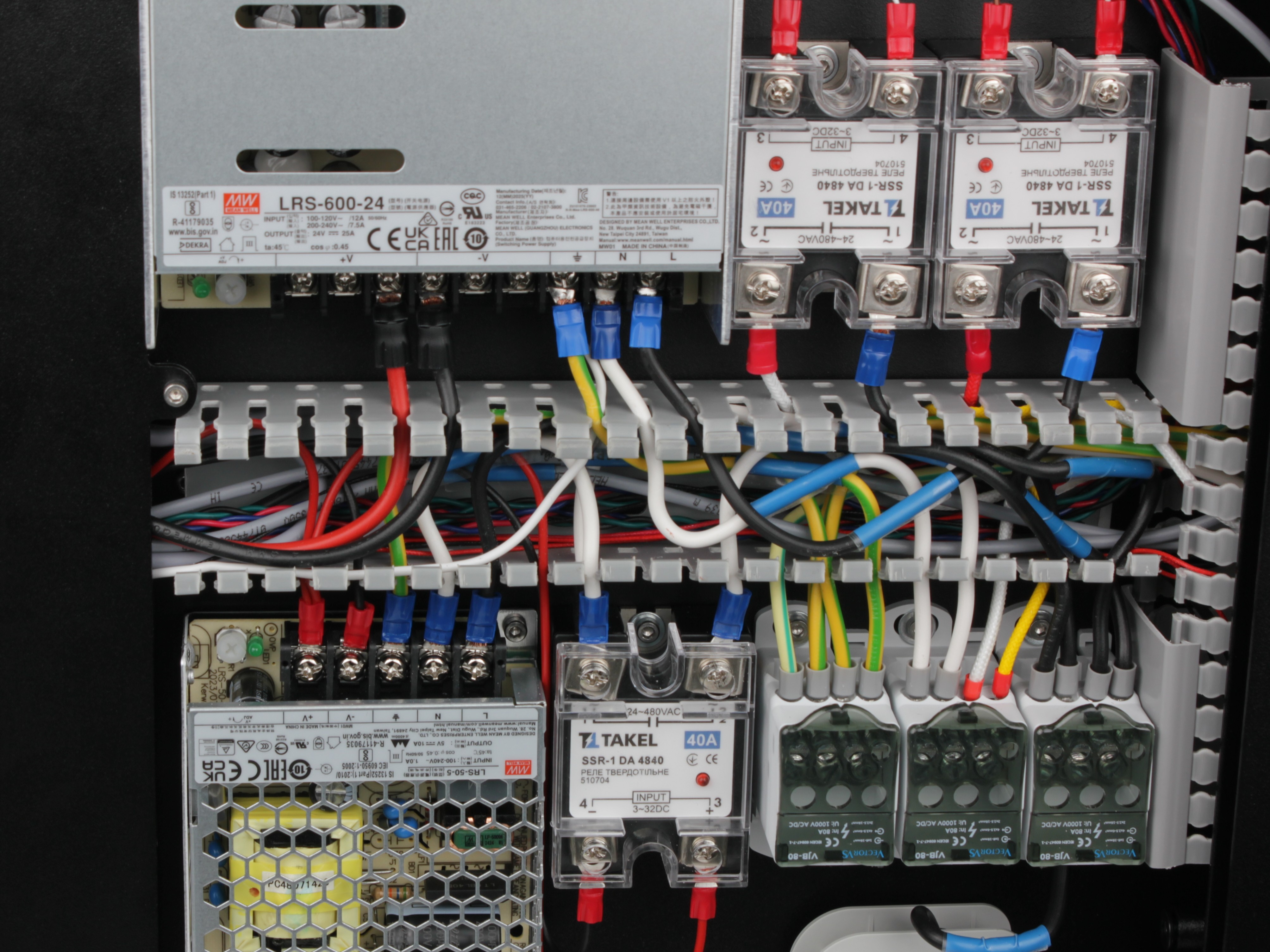
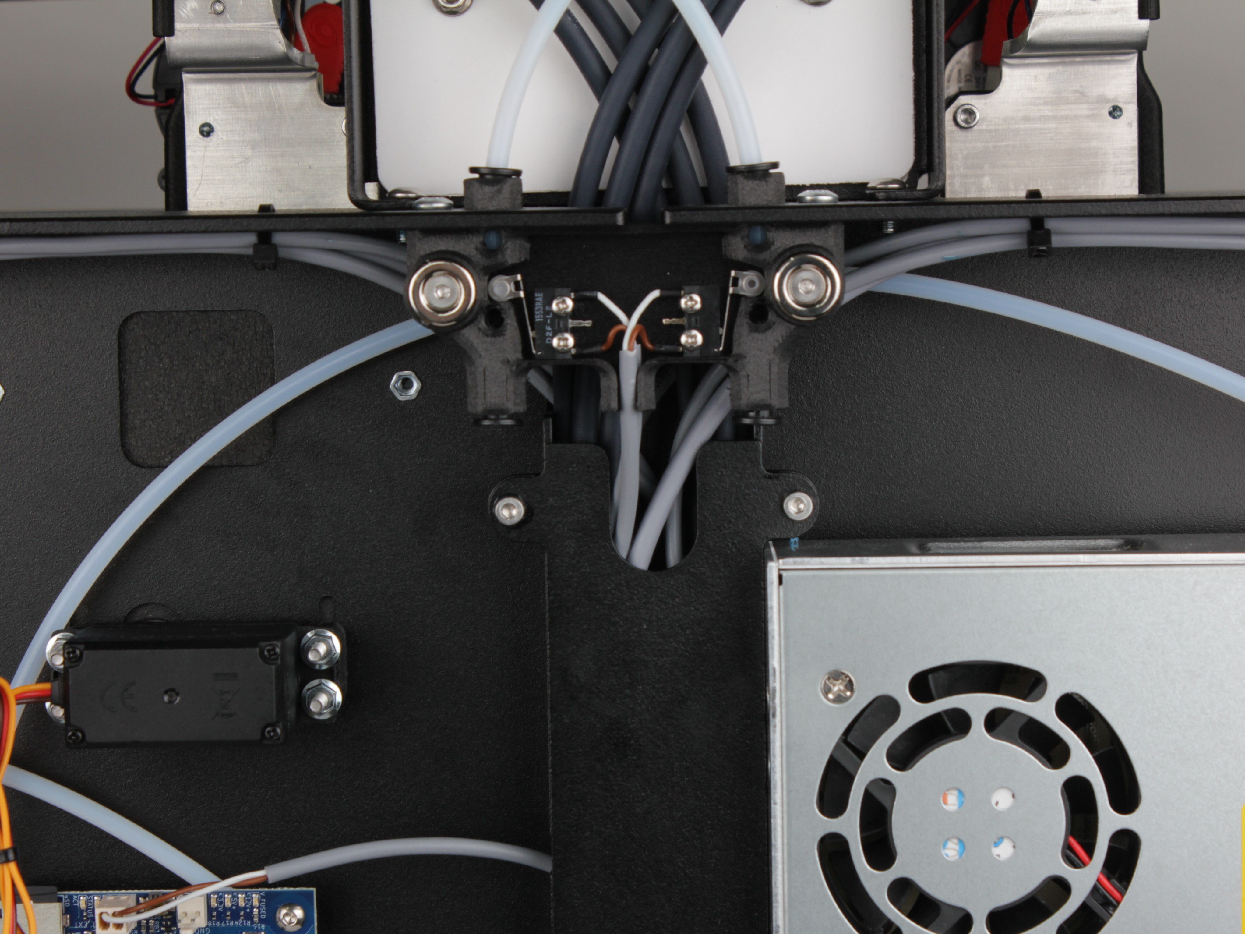
View with the cable channel cover removed
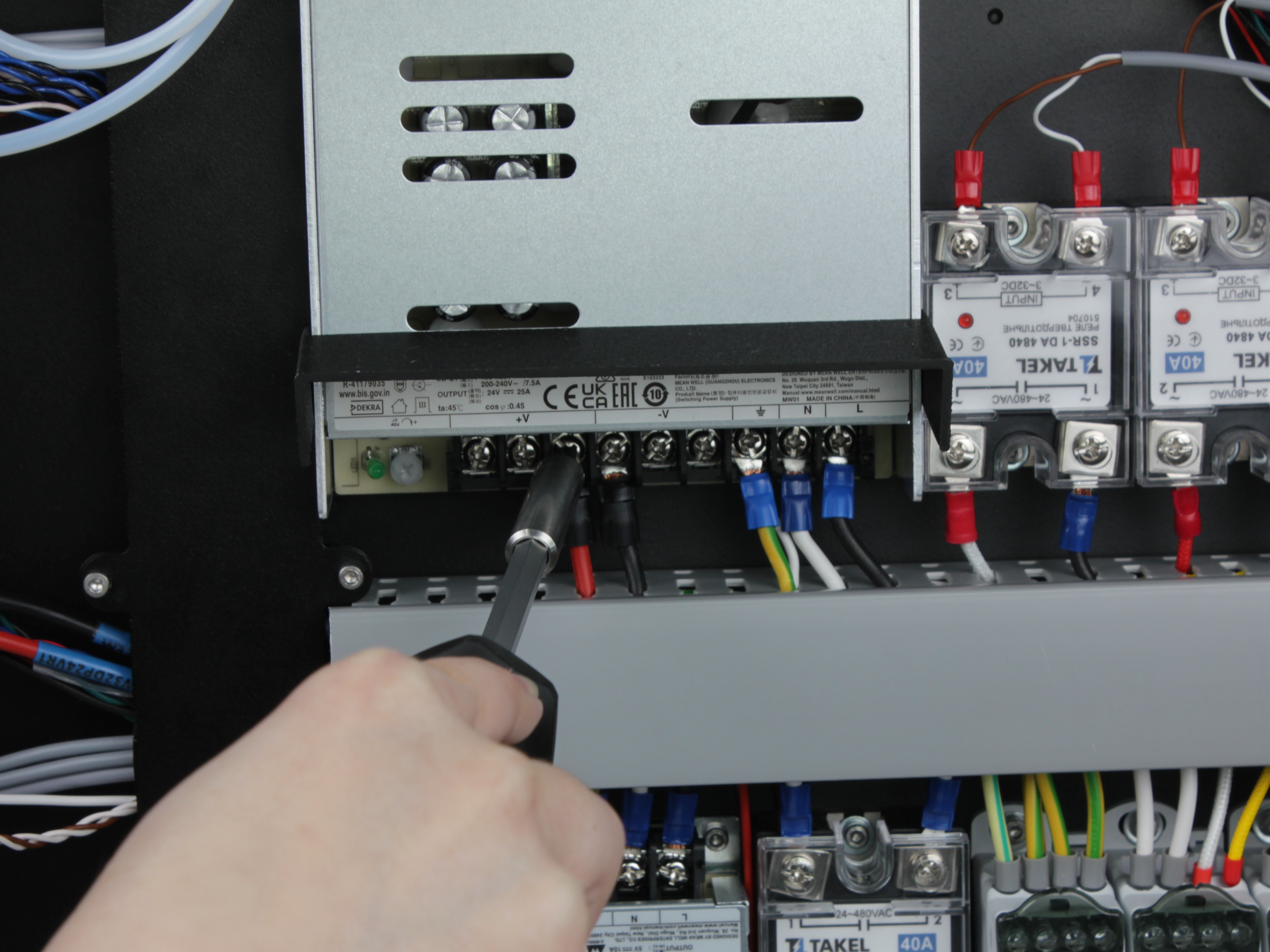
Disconnecting the Terminals
Treat PSU terminals as live – use insulated tools
Even after waiting 60 seconds, treat all PSU terminals as potentially live. Do not touch bare metal contacts with your fingers. Use insulated tools.
8. Using a PH2 Phillips screwdriver, loosen all terminal screws on the PSU and disconnect all wires.
Disconnect both the input side (mains AC) and the output side (24V DC).
9. Gently push the disconnected wires down and away from the PSU.
This prevents them from interfering with PSU removal.
Removing the T0 Filament Tube
10. Remove both PTFE filament tubes from the filament sensor endstop holder.
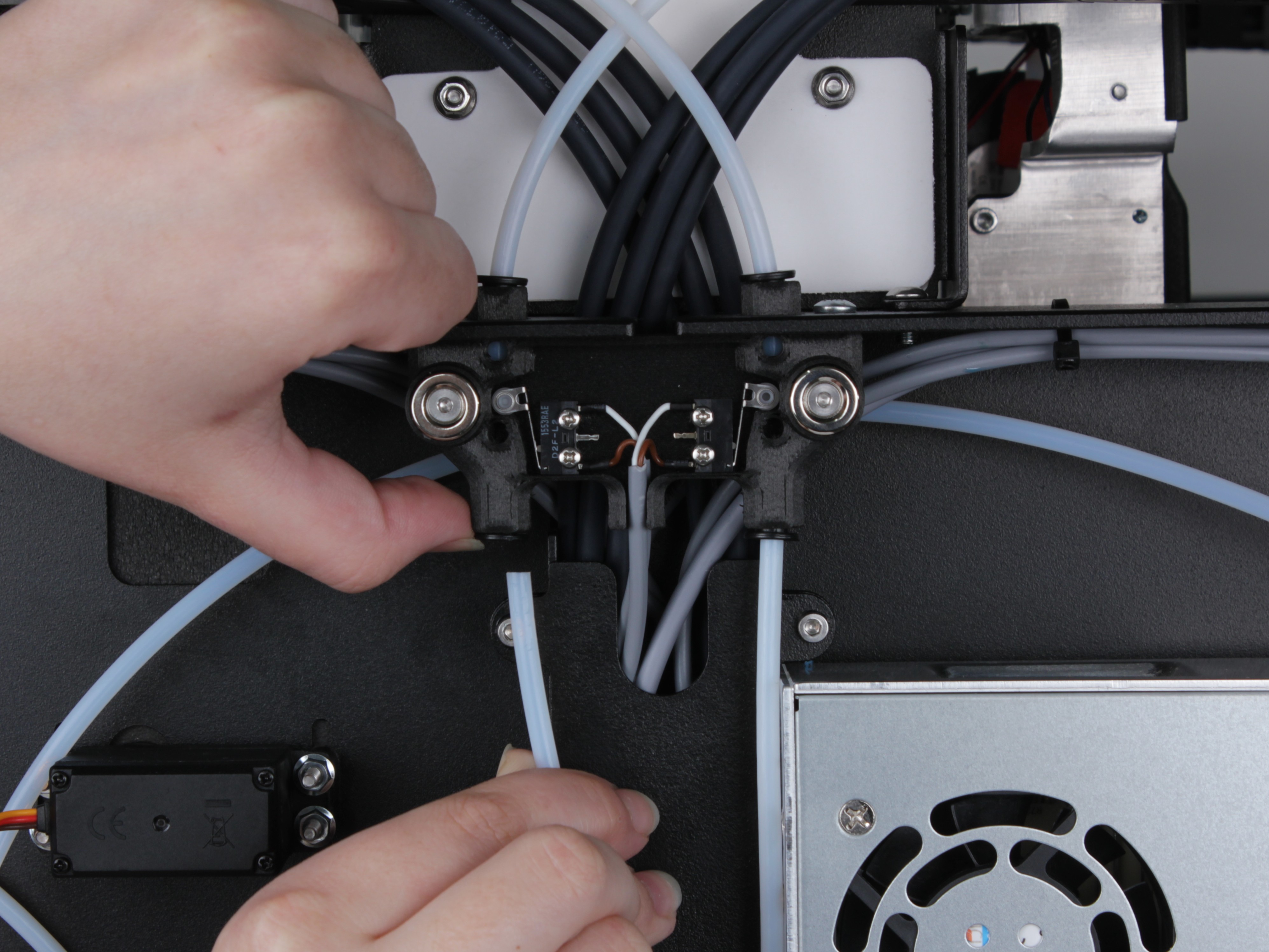
11. Remove both tubes from the L-shaped tube holder.
12. From the other end, remove the T0 filament tube from the tube holder and pull it out of the ring-shaped holder to free it from the printer.
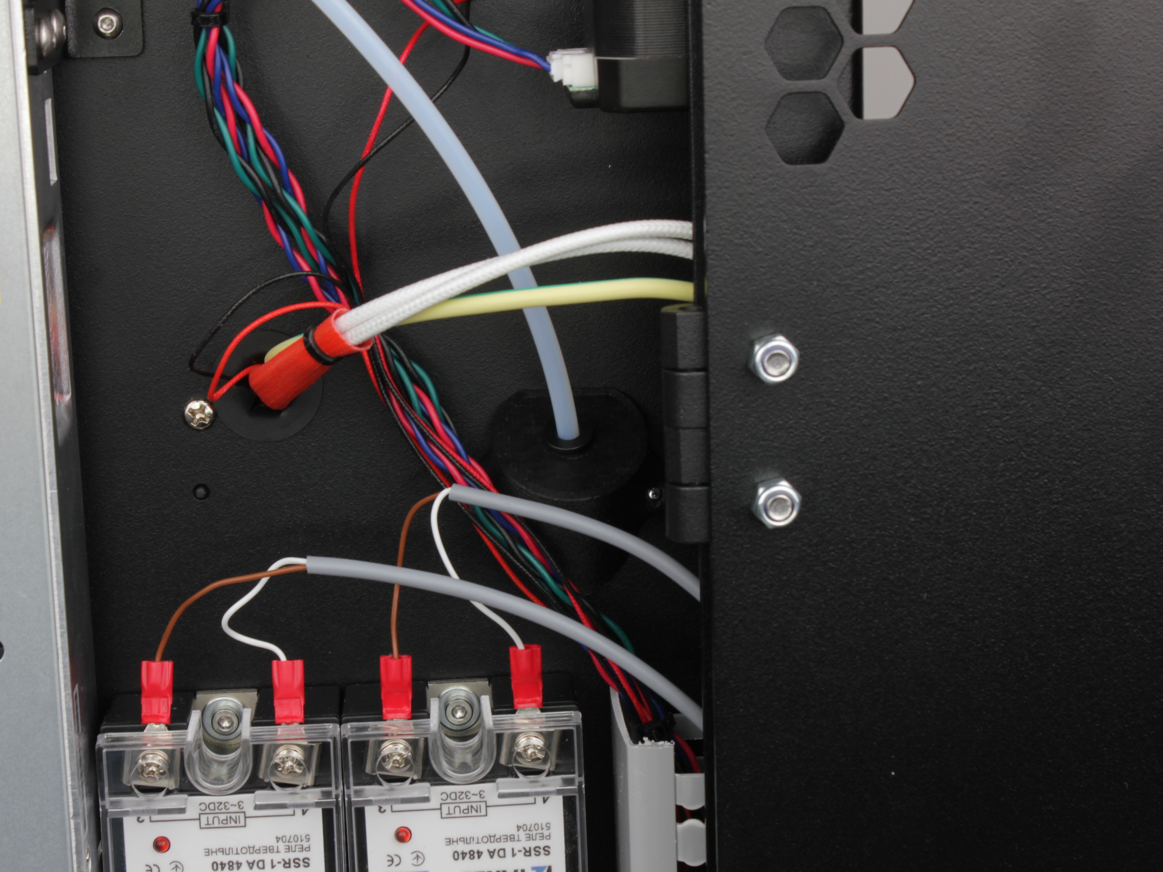
Removing the Vertical Cable Channel Cover
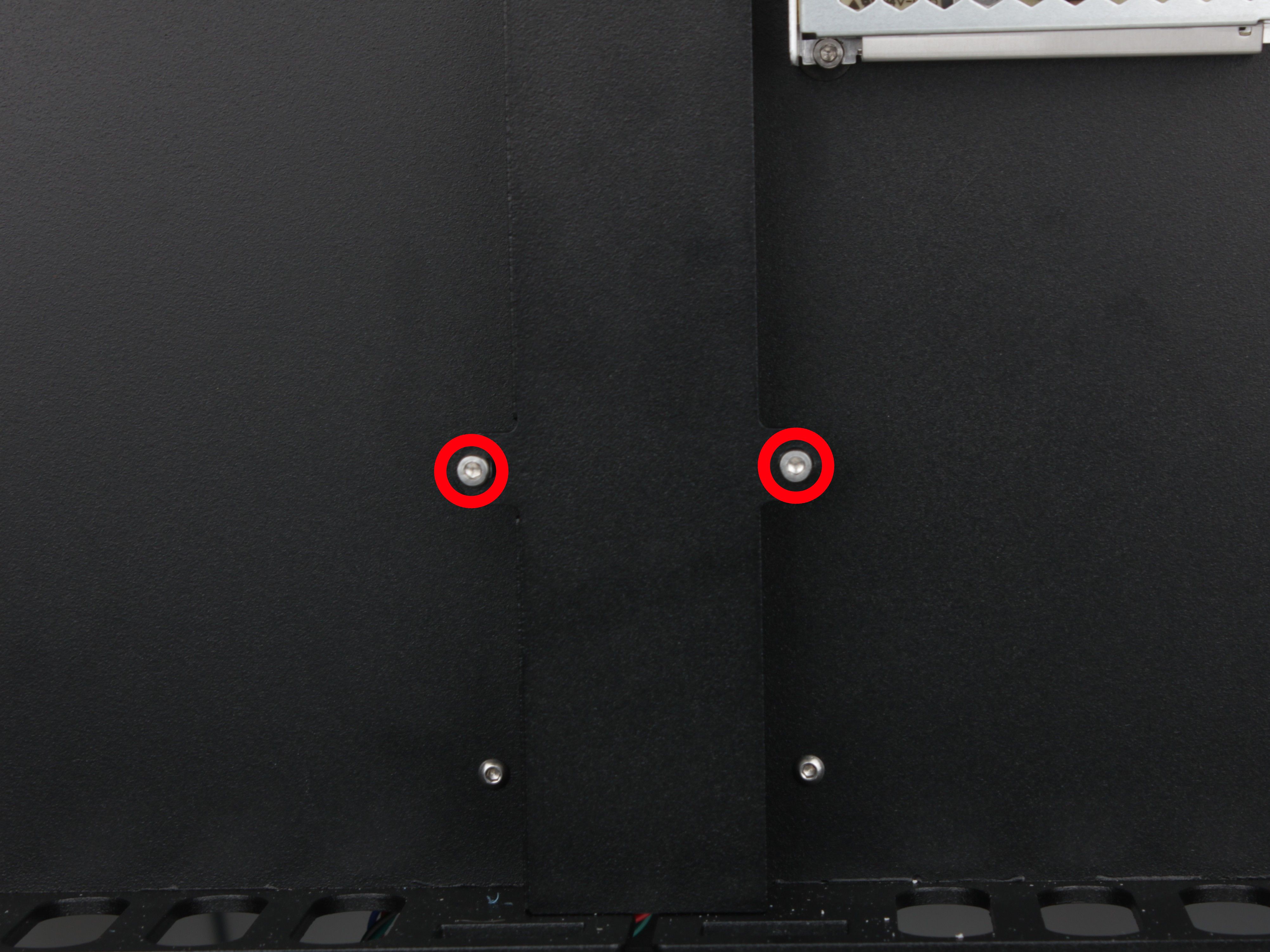
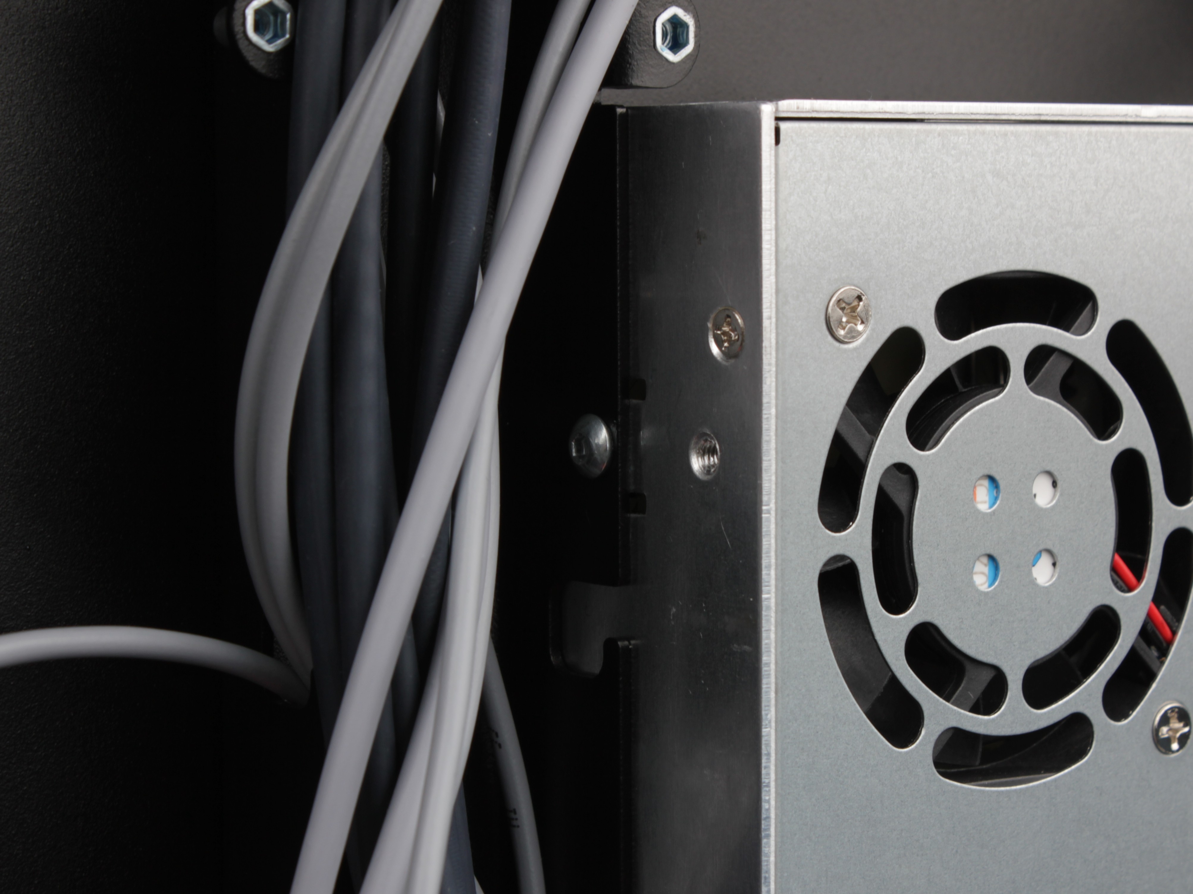
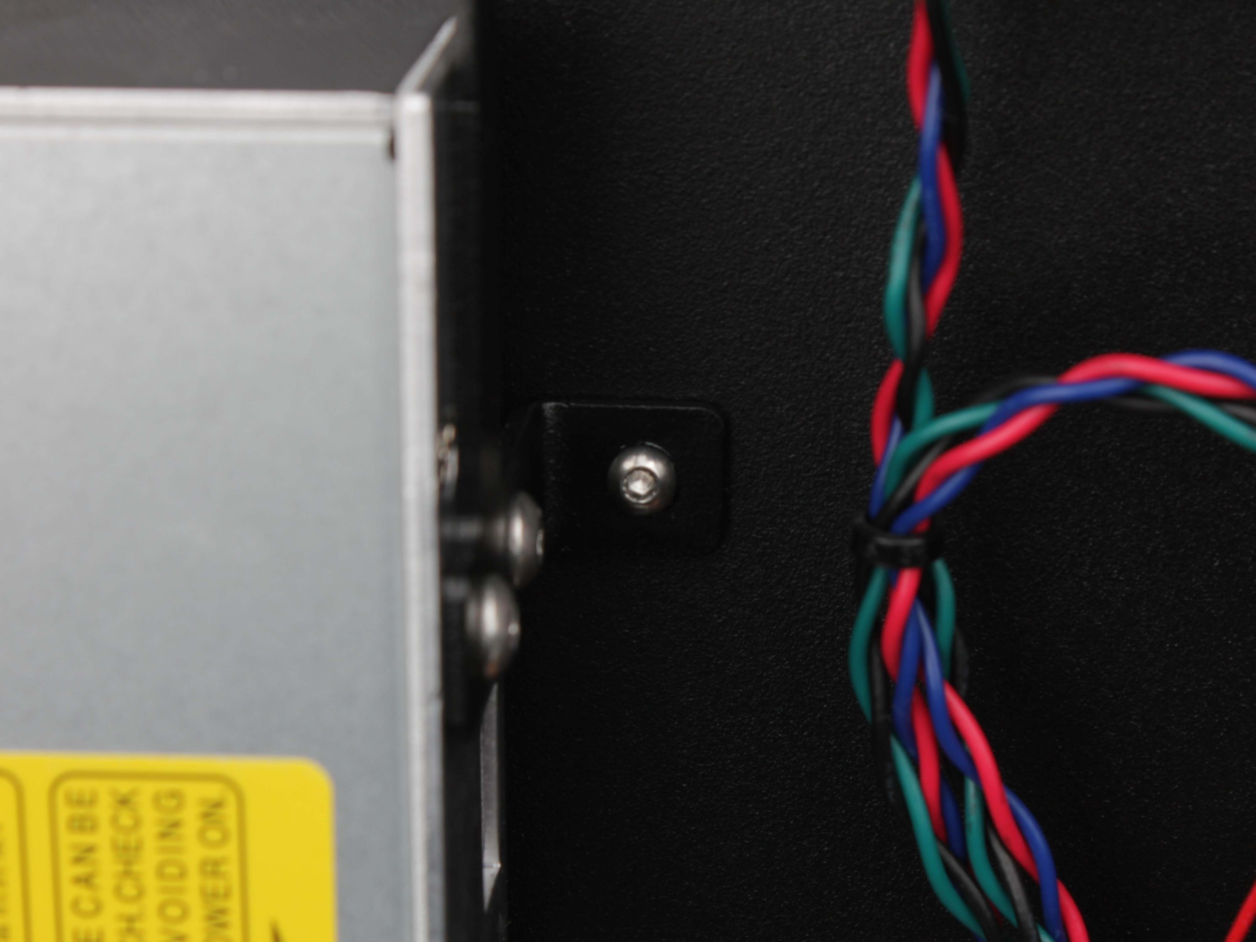
13. On the left side of the PSU, locate the vertical metal cable channel. Unscrew its cover.
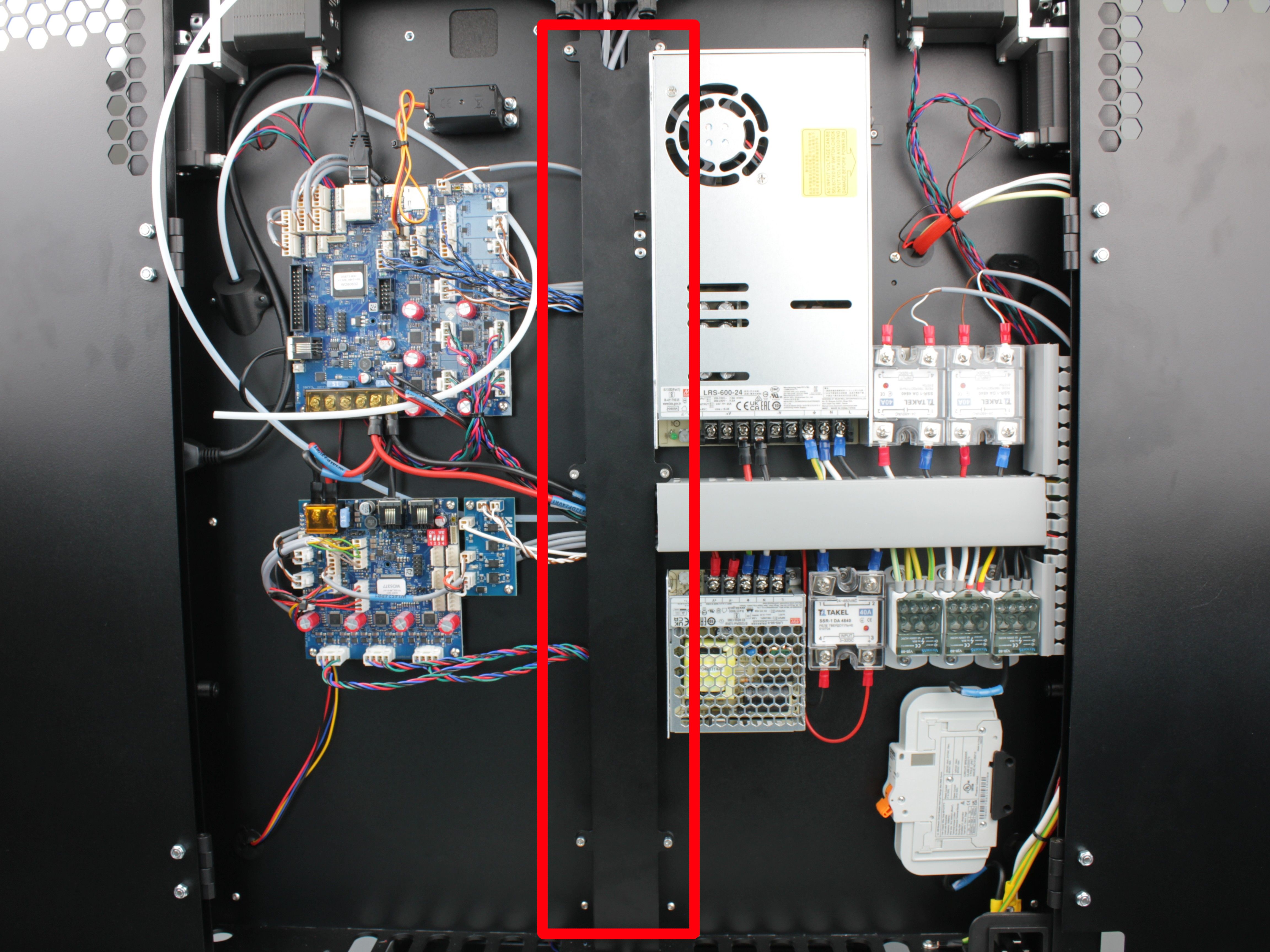
General view of the vertical cable channel cover
Position of the upper screws
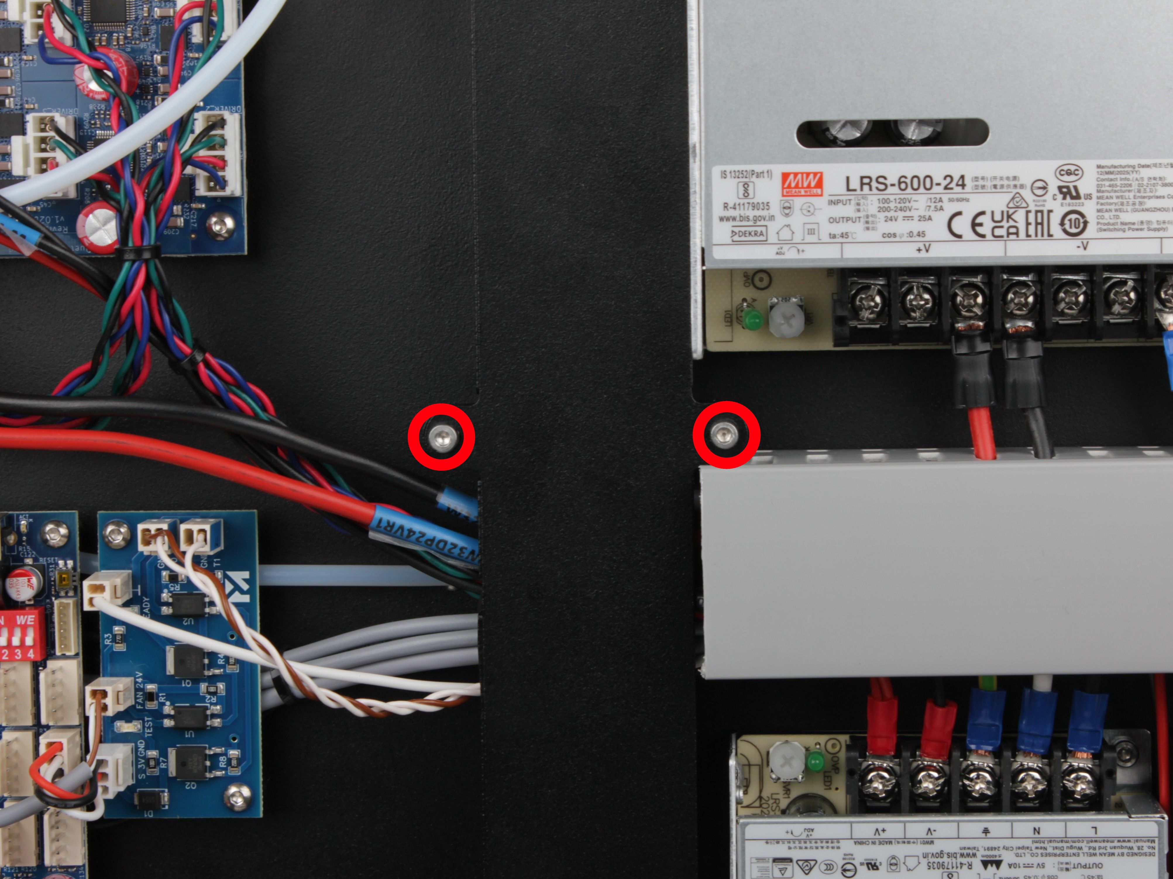
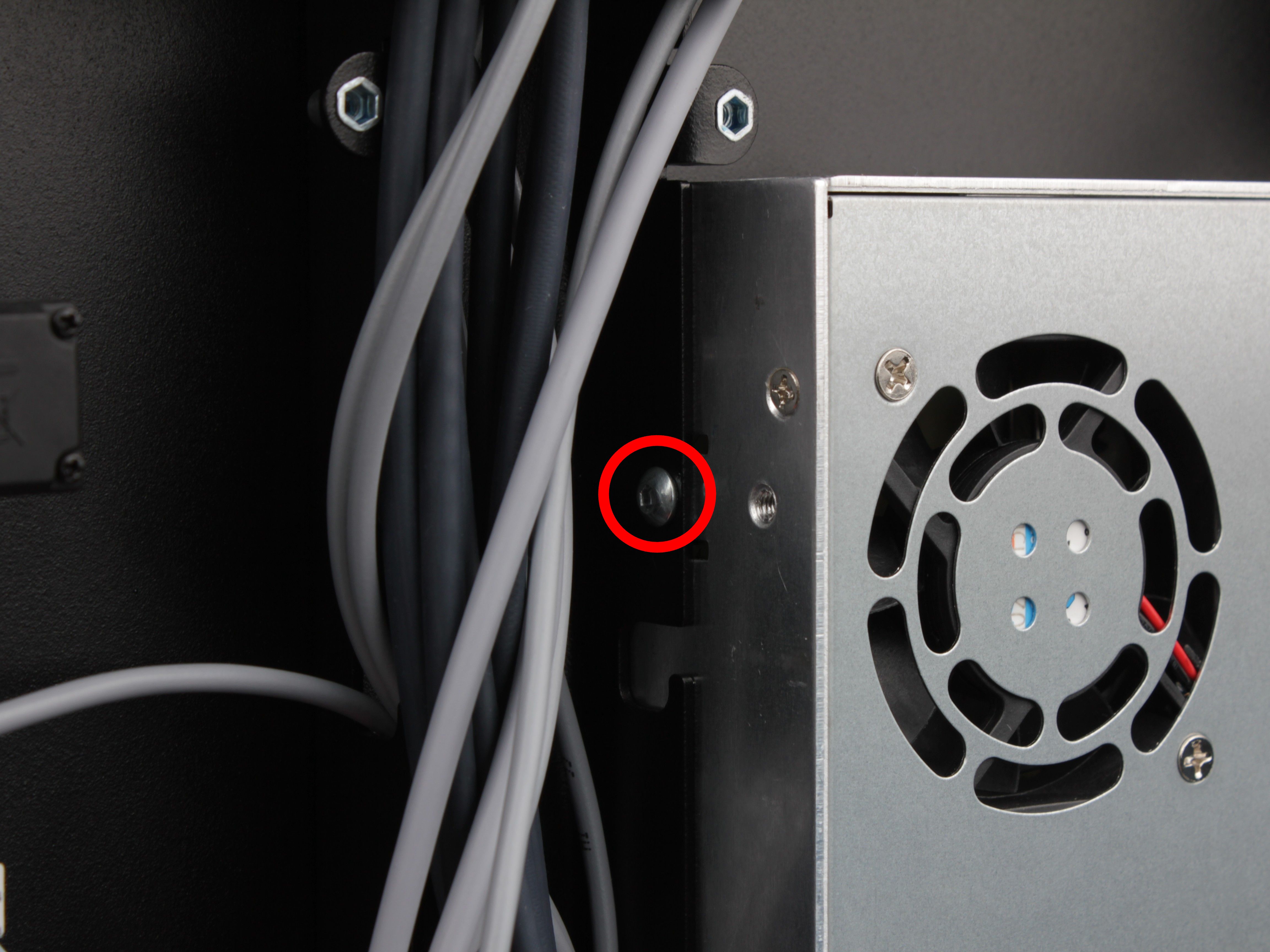
Position of the middle screws
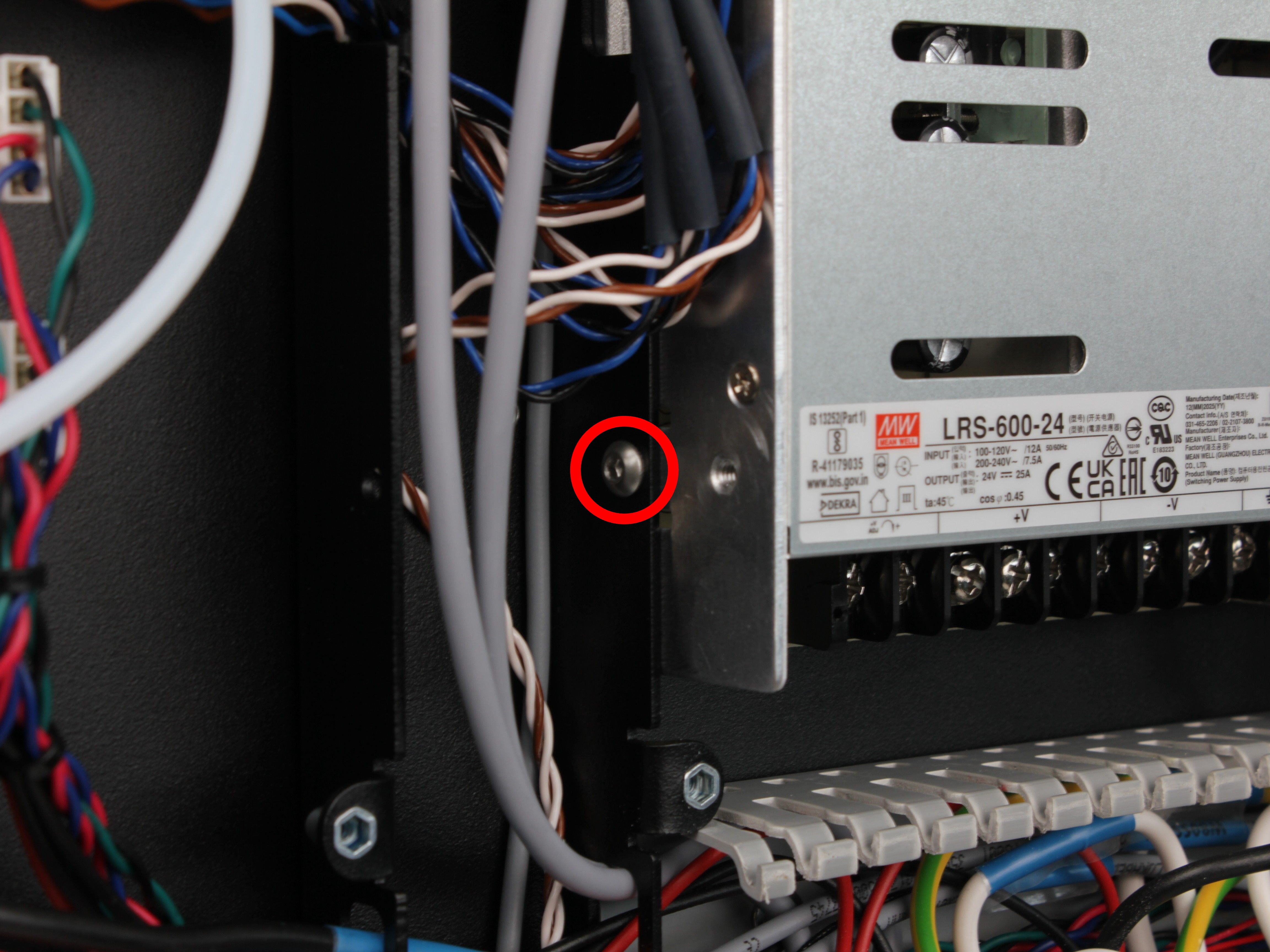
Position of the lower screws
14. Remove the cover.
The PSU is held on the left side by two mounting screws. Both screws are hidden under the vertical cable channel cover.
Removing the PSU
15. Unscrew both mounting screws on the left side using a 2.5 mm hex screwdriver.
Upper PSU mounting screw (left side)
Lower PSU mounting screw (left side)
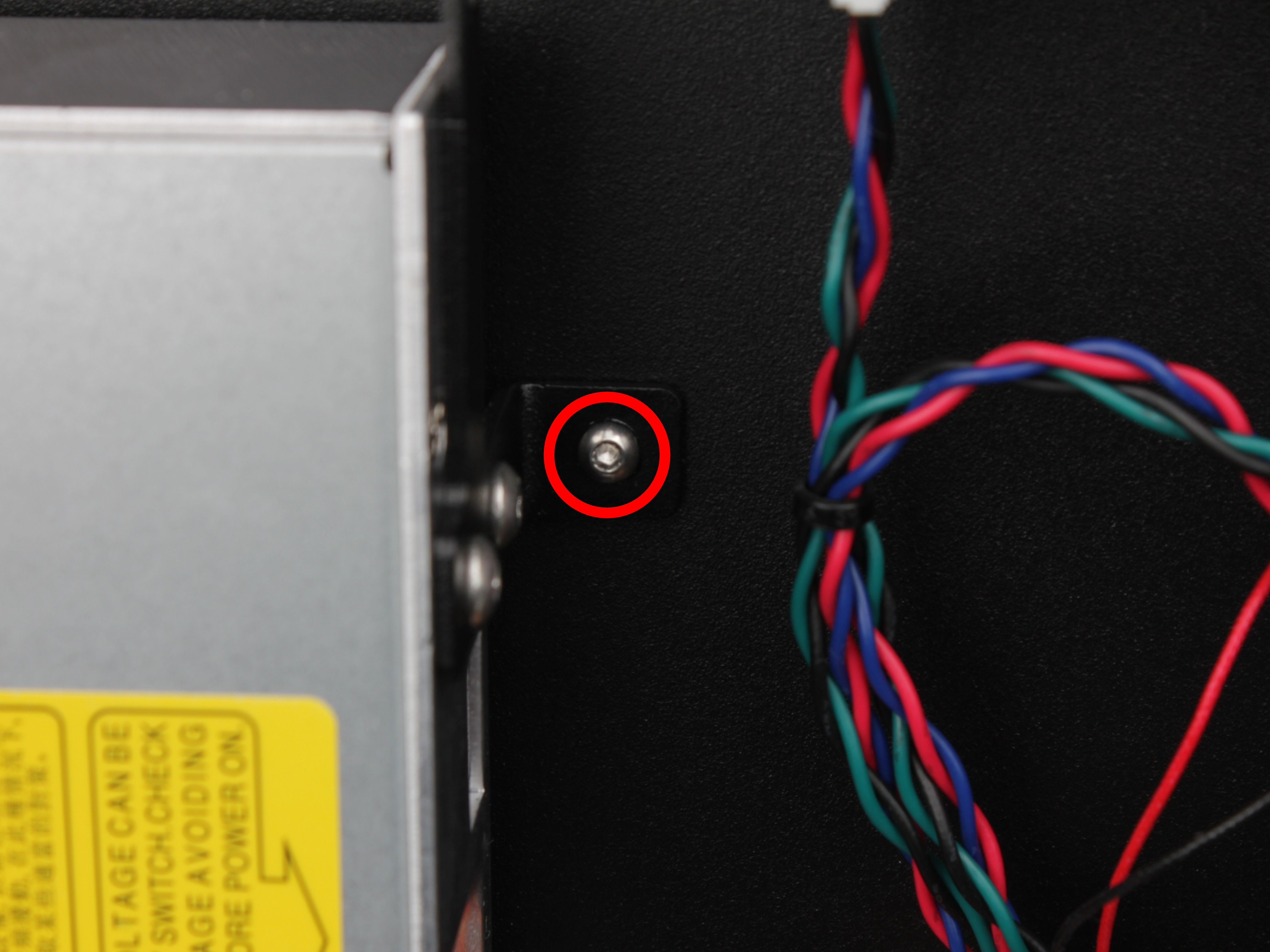
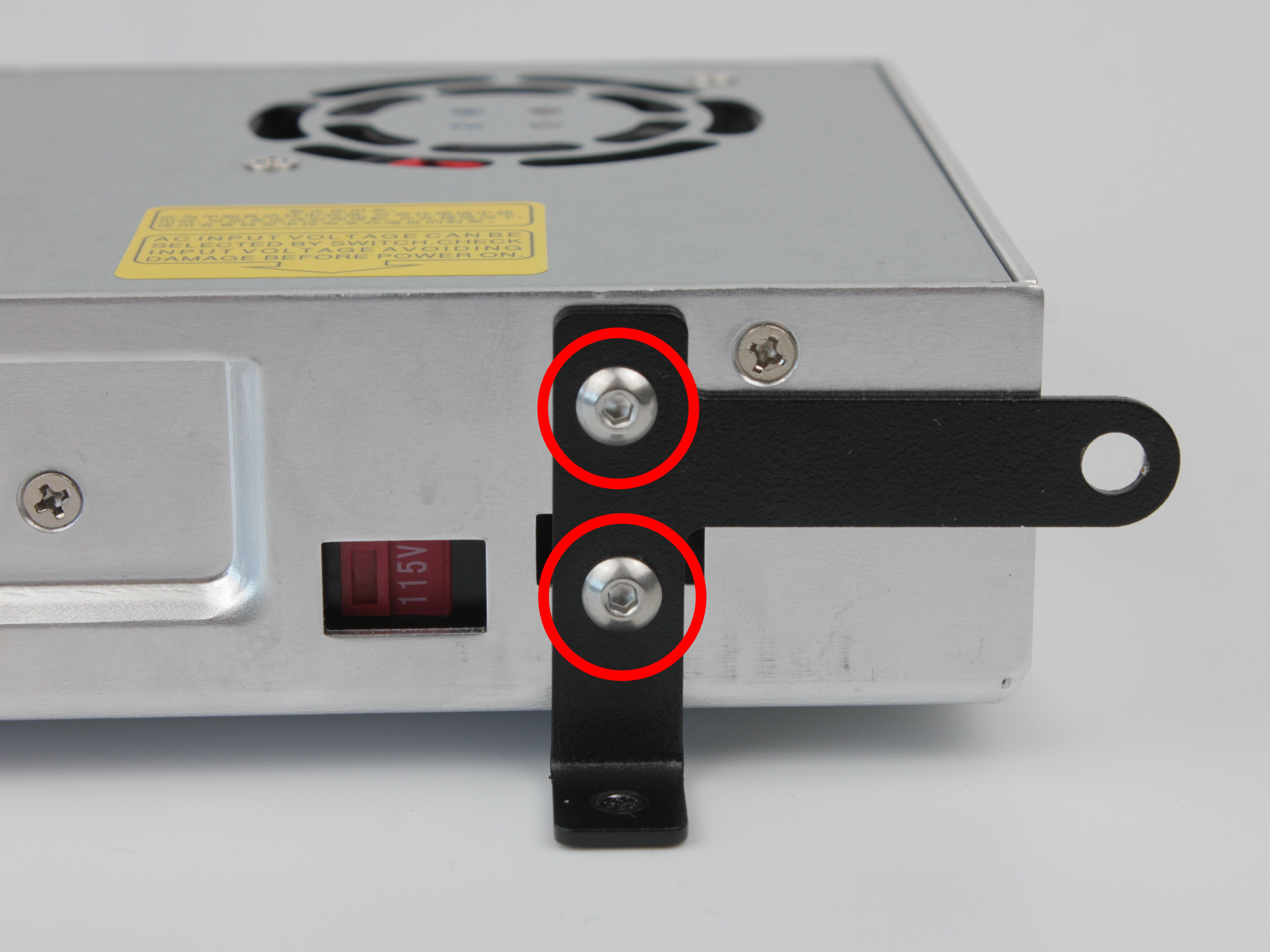
16. On the right side of the PSU, unscrew the single screw that secures the L-shaped bracket to the chassis.
17. Lift the PSU out of the chassis.
The L-shaped bracket stays attached to the PSU (held by two screws).
Transferring the Bracket
18. Unscrew the two screws that attach the L-shaped bracket to the old PSU.
19. Attach the L-shaped bracket to the new PSU with the same two screws in the same orientation.
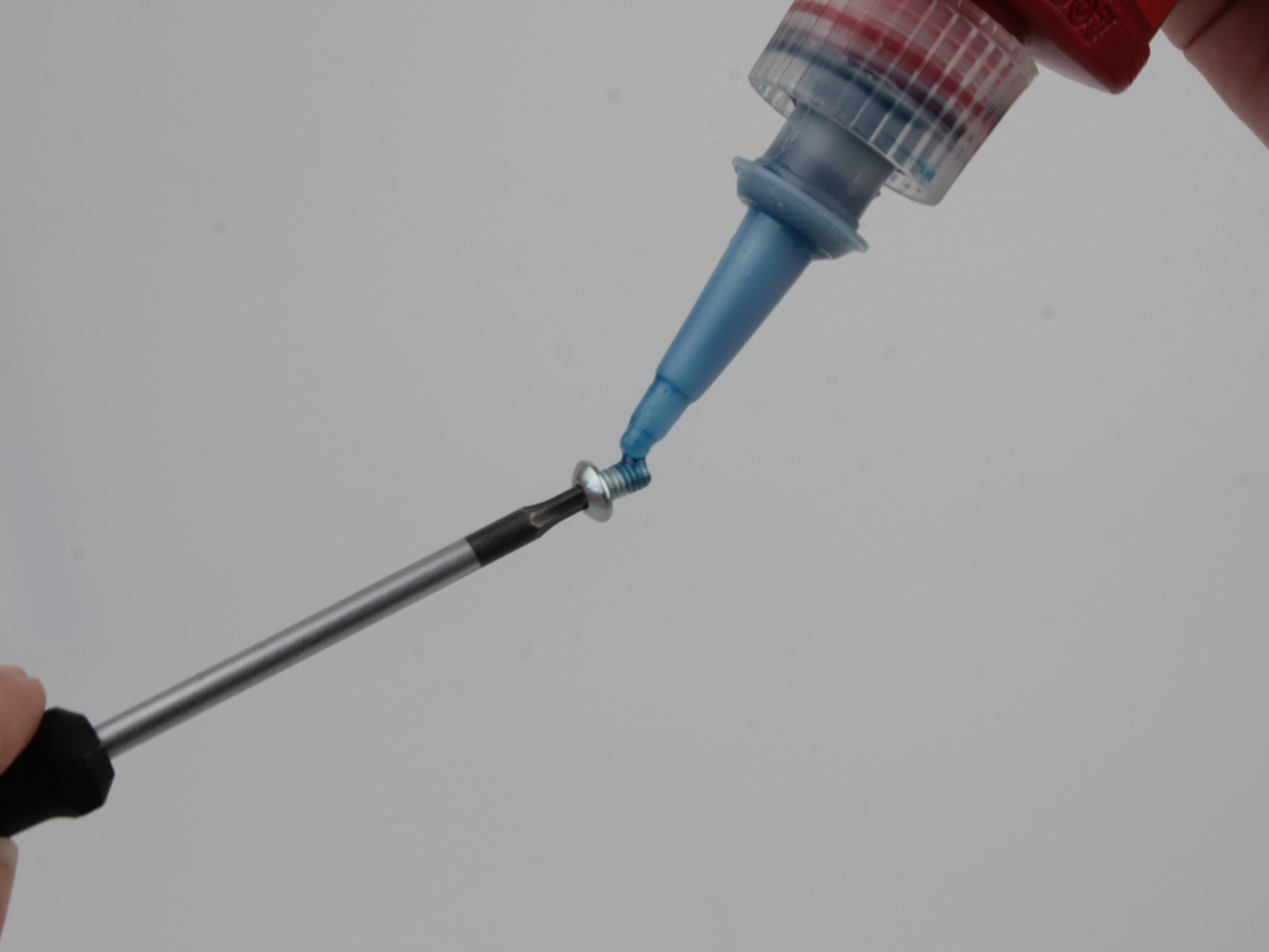
Apply threadlocker to both screws before tightening.
Installing the New PSU
20. Place the new PSU (with bracket attached) into the chassis in the same position as the old one.
21. On the left side, reinstall the two mounting screws.
Apply threadlocker to both screws before tightening.
Upper PSU mounting screw (left side)
Lower PSU mounting screw (left side)
22. On the right side, secure the L-shaped bracket to the chassis with its single screw.
Apply threadlocker before tightening.
L-shaped bracket secured to chassis (right side)
Reconnecting the Wiring
Match every wire to your reference photos
Refer to your photos. Every wire must go back to the exact same terminal, in the same position. Incorrect wiring can damage the printer or create a fire hazard.
23. Reconnect all wires to the new PSU terminals.
Reconnect both mains input and 24V DC output, matching the exact positions from your reference photos. Tighten each terminal screw firmly.
24. Reinstall the 3D-printed protective terminal cover and secure with two 2.5 mm hex screws.
25. Route the T0 filament tube back through the ring-shaped holder and the tube holder.
Place both tubes into the L-shaped holder, then insert both tubes into the filament sensor endstop holder.
26. Reinstall the vertical cable channel cover on the left side and secure it with the same screws removed earlier.
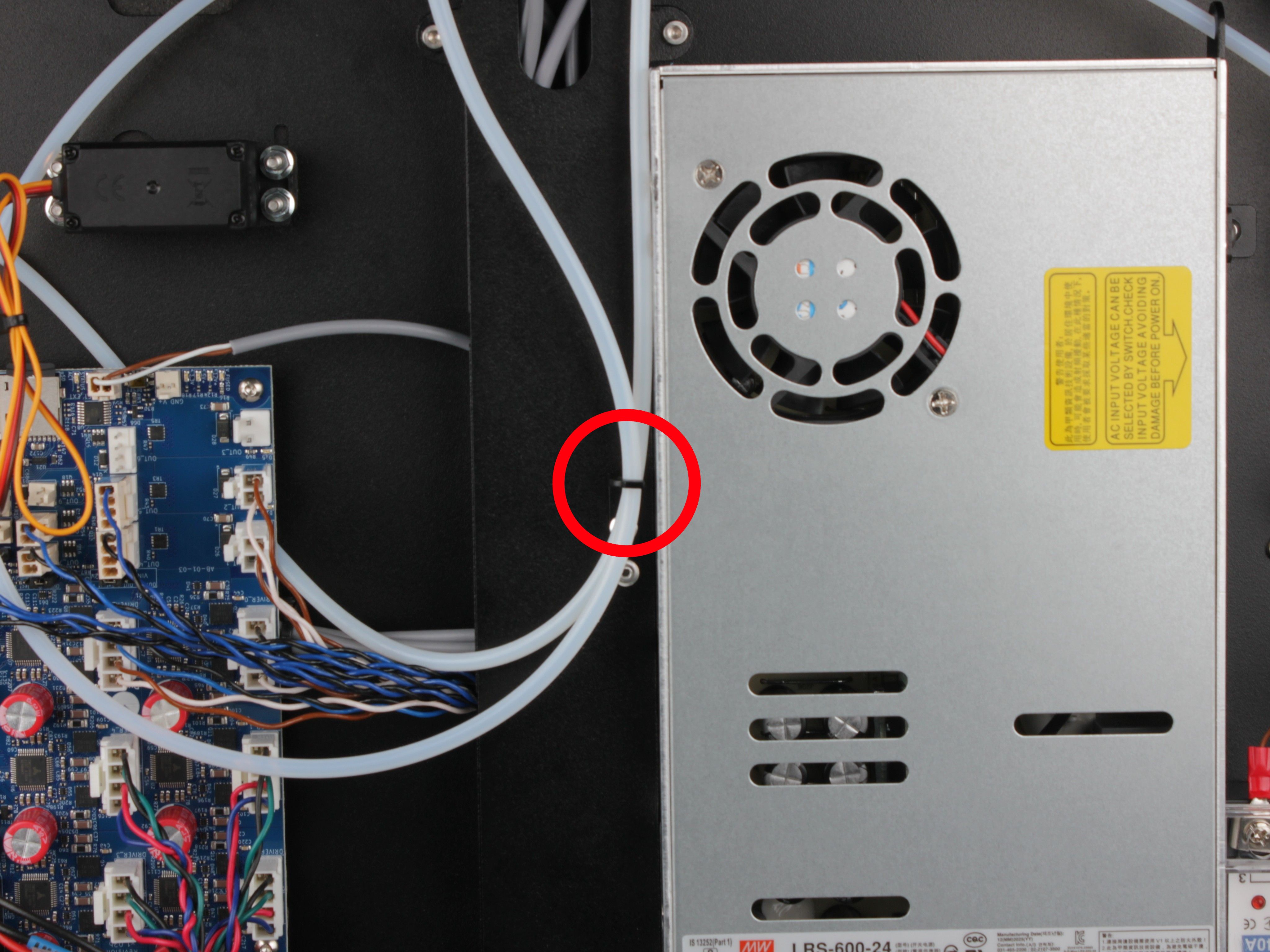
27. Snap the bottom cable channel cover back into place.
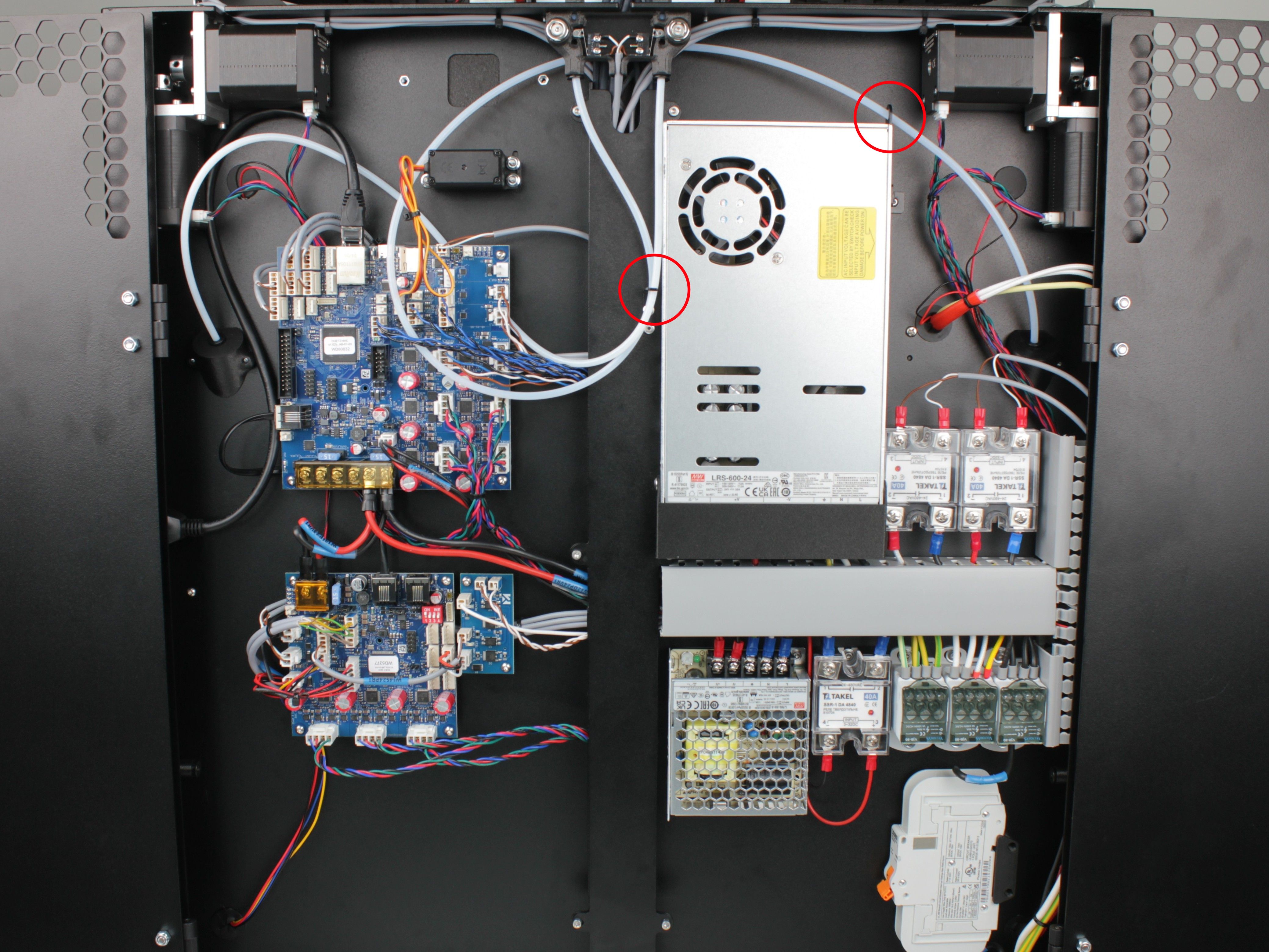
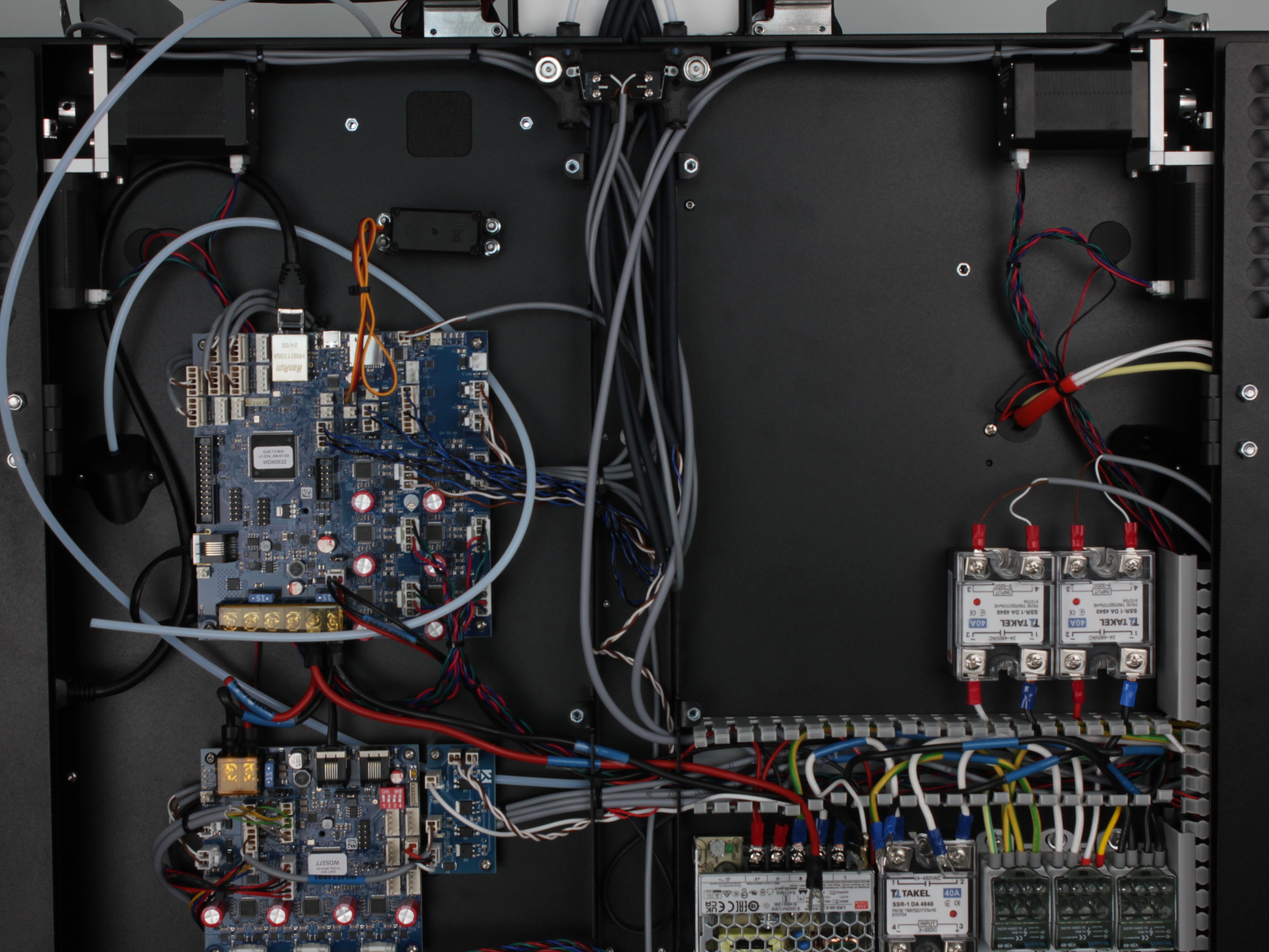
Overview of the fully reassembled electronics bay. In the photo, highlight (e.g. red circles): filament tube must pass through the ring-shaped holder and the L-shaped holder – verify both before closing the bay.
Final Checks and Re-Torque
28. Double-check all terminal connections against your reference photos.
Verify no wires are loose, crossed, or pinched.
29. Close the rear electronics bay.
30. Plug in the mains power cable and power on the printer.
Verify the printer boots normally and the 24V rail is functioning (check via the Web Interface dashboard).
Re-tighten PSU terminals after one day of operation
After one day of normal printer operation, power off the printer, unplug it, wait 60 seconds, and re-tighten all PSU terminal screws. Thermal cycling during initial use can cause terminals to loosen slightly.
31. After one day of operation, turn off and unplug the printer.
Wait 60 seconds, then open the rear electronics bay and re-tighten all PSU terminal screws (both input and output).
FAQ
Troubleshooting
Support
If you could not find an answer here, reach out to our support team.