Filament PTFE Tube
This guide covers how to replace worn or damaged filament PTFE tubes on the Vision Miner 22IDEX V4. The printer uses PTFE tubes to guide filament from the rear of the machine to the extruder. Over time, tubes can wear out, get kinked, or become compressed – especially on the front section that moves with the toolheads on the cable chains.
Before you begin - safety and risk
Read the Safety - Before You Begin article to understand the hazards involved in working on the Vision Miner 22IDEX V4 - including electrical, thermal, mechanical, and chemical risks. All procedures in this wiki are provided as recommendations only. By choosing to follow any procedure, you do so at your own risk.
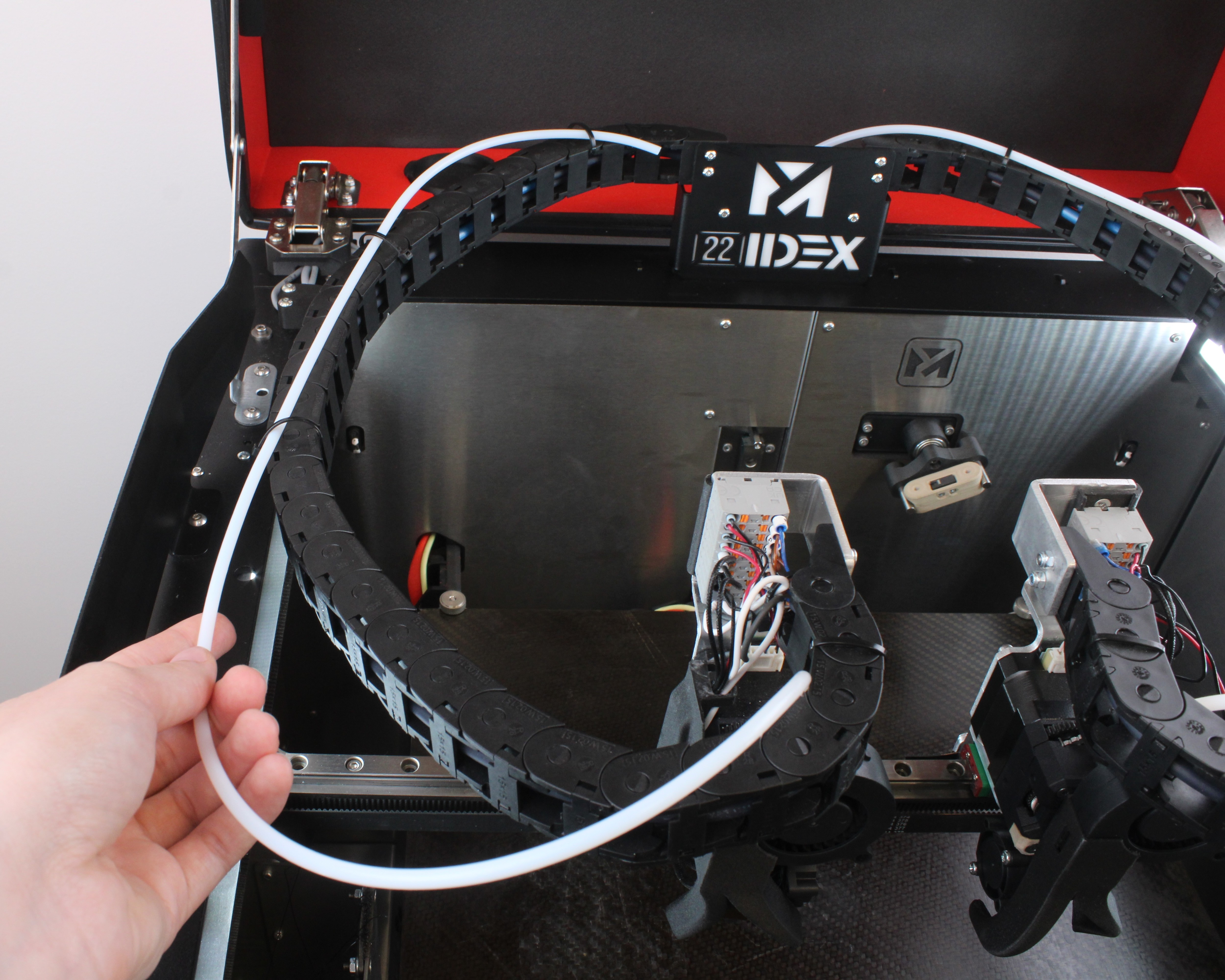
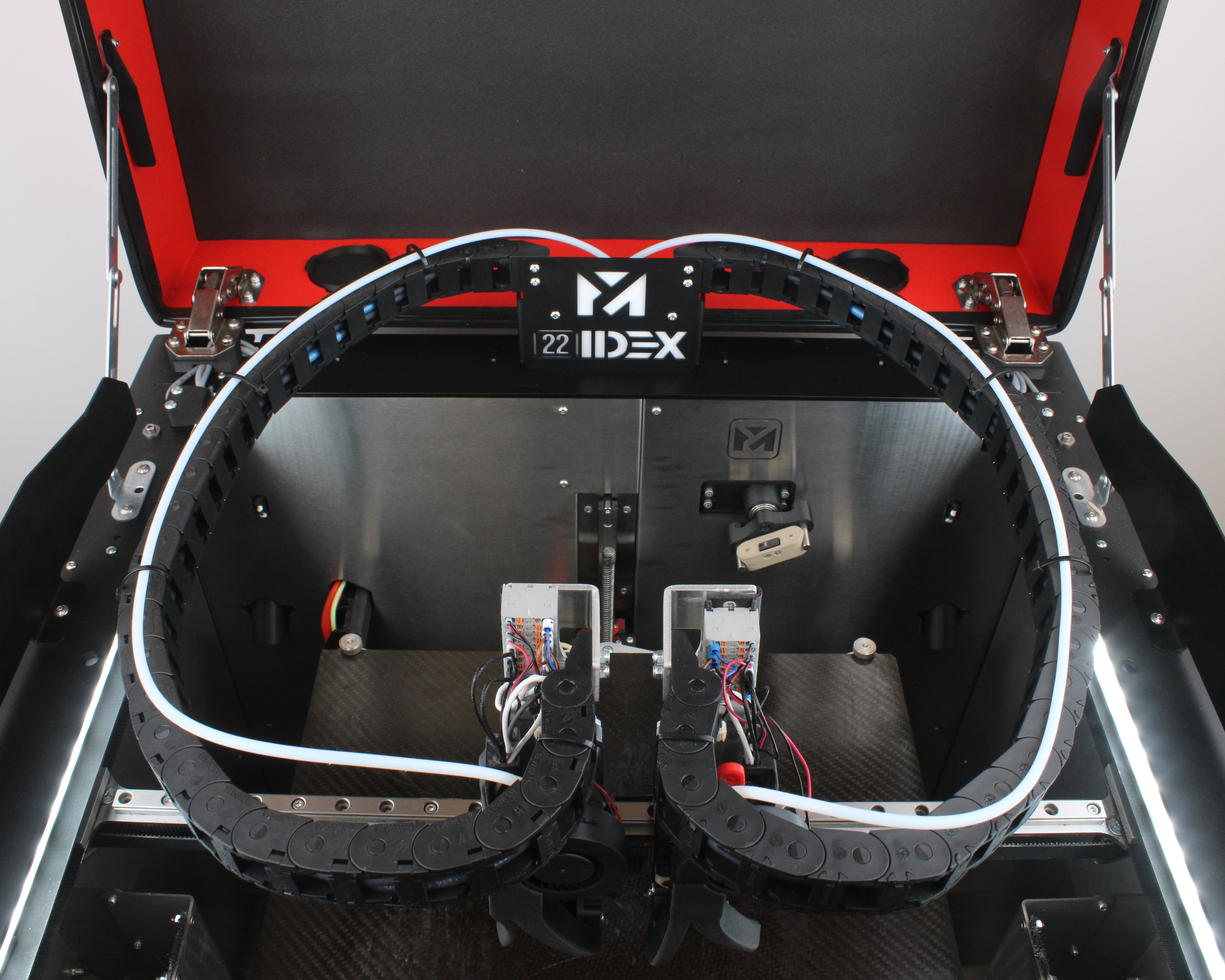
Tube Layout
The Vision Miner 22IDEX V4 has two PTFE tube sections per filament path:
Rear tube – runs from the rear wall filament entry to the upper portal filament sensor. The rear tubes have different lengths for T0 and T1 – T0 has a longer path, T1 is shorter. Wear risk is lower because the tube is stationary, but it can compress if the spool tangles.
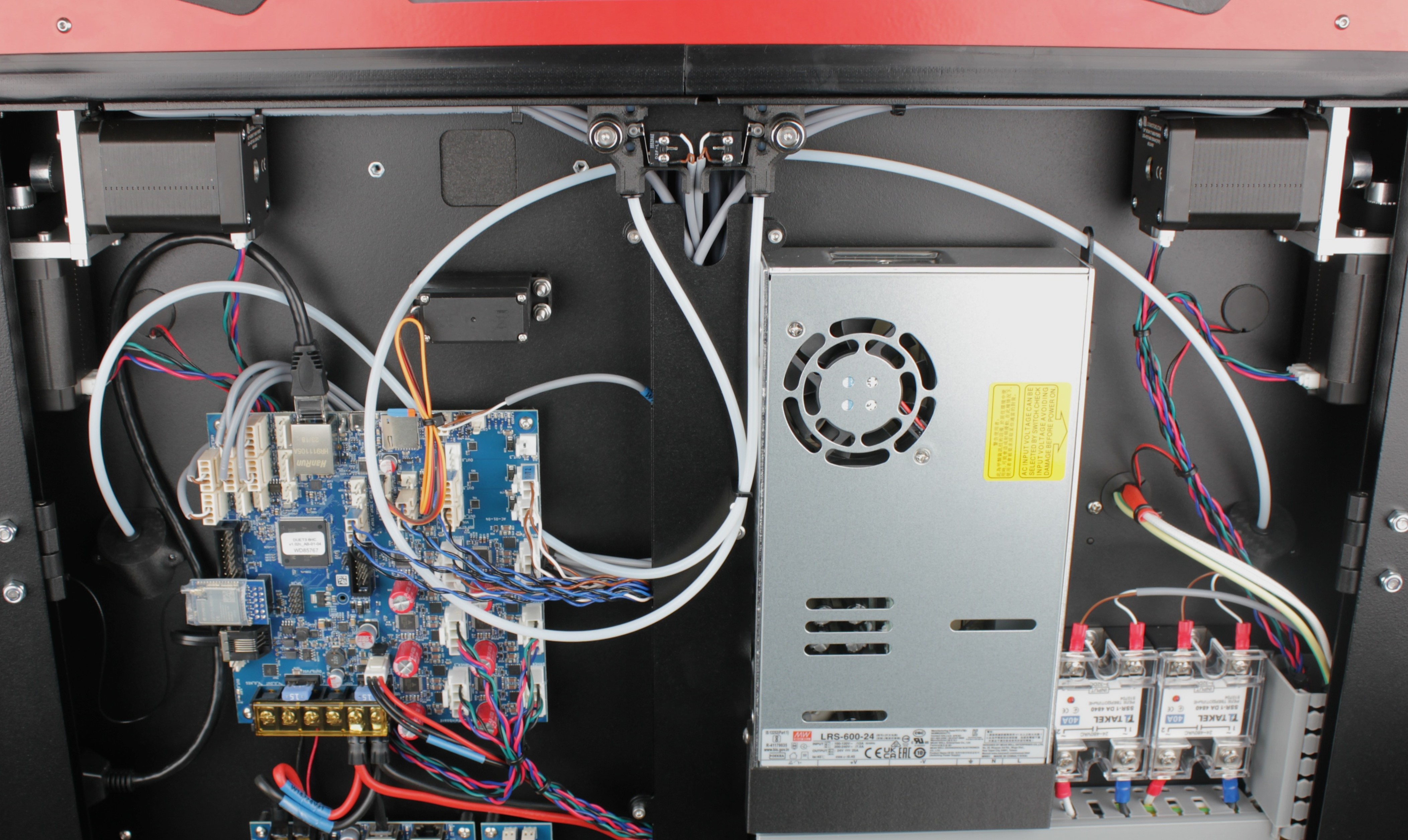
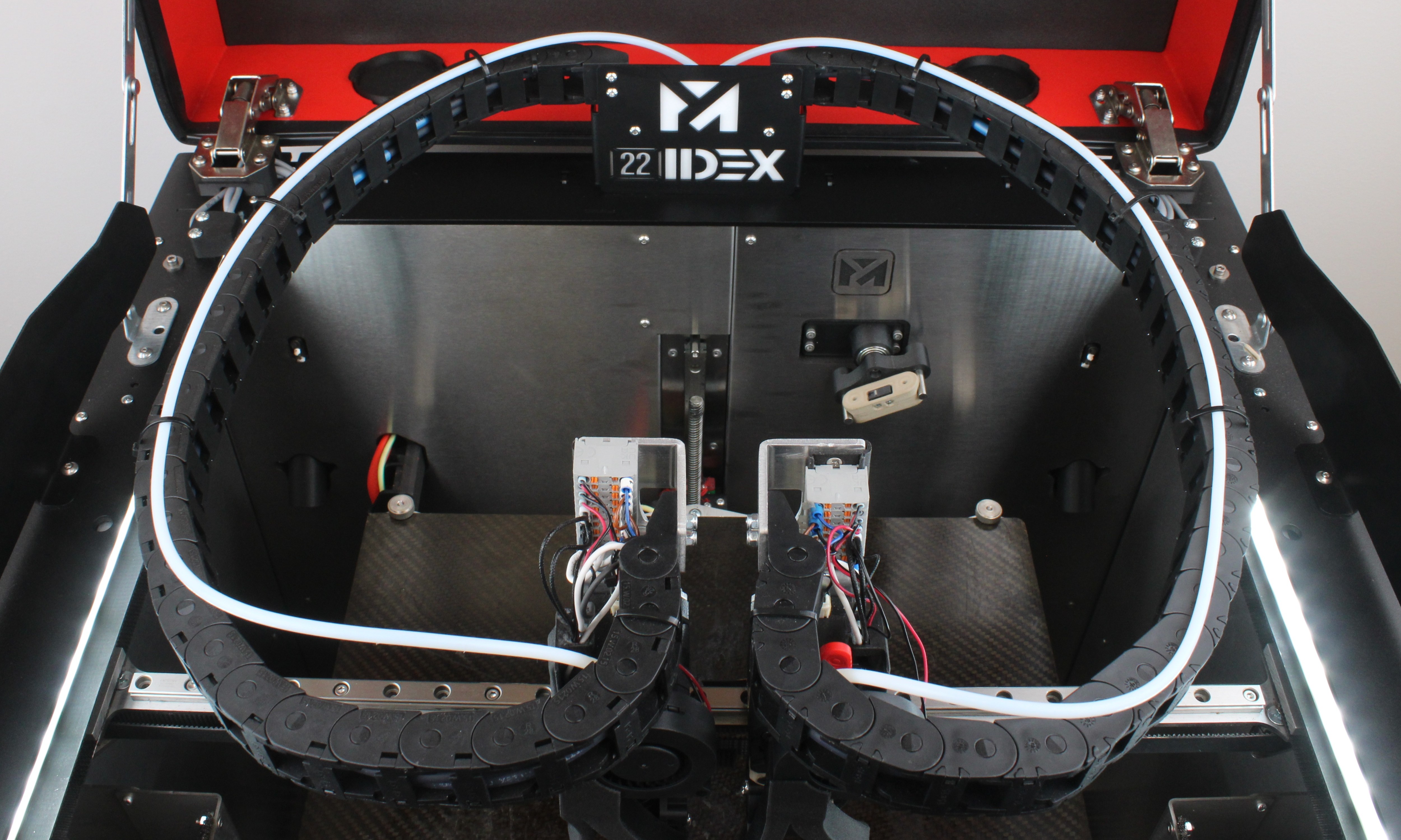
Front tube – runs from the upper portal filament sensor to the extruder. The front tubes are the same length for both T0 and T1. Wear risk is higher because the tube hangs on the cable chain and moves constantly with the toolhead.
When ordering replacement tubes, pay attention to both the diameter and the length of the tube. The rear tubes for T0 and T1 have different lengths, while the front tubes are identical.
The front tubes wear faster because they are attached to the cable chains and move continuously during printing. They can get kinked by stiff filament or pulled out of shape over time. For stiff materials, you can reroute the rear tubes to follow gentler curves.
Tools and Materials
- Replacement PTFE tube (correct diameter and length for your filament path – note that rear tubes differ in length between T0 and T1)
- No special tools required – tubes use push-fit (quick-release) connectors
Replacing the Front Tube (Sensor to Extruder)
This is the tube that runs from the filament sensor in the upper portal down to the extruder on the toolhead. It travels through the cable chain and is the most common tube to need replacement.
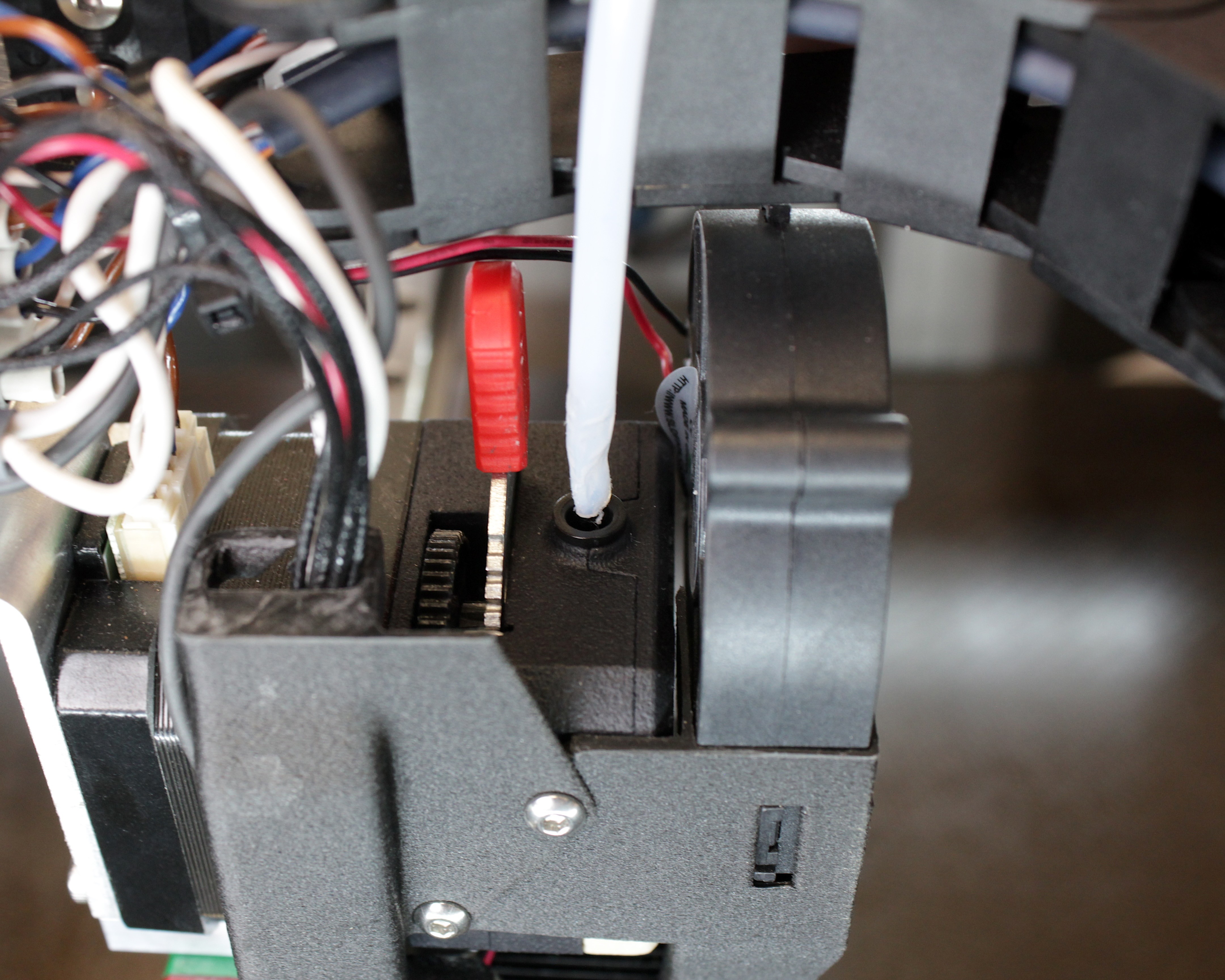
- Locate the PTFE tube where it connects to the extruder. There is a push-fit clip (collet) holding the tube in place.
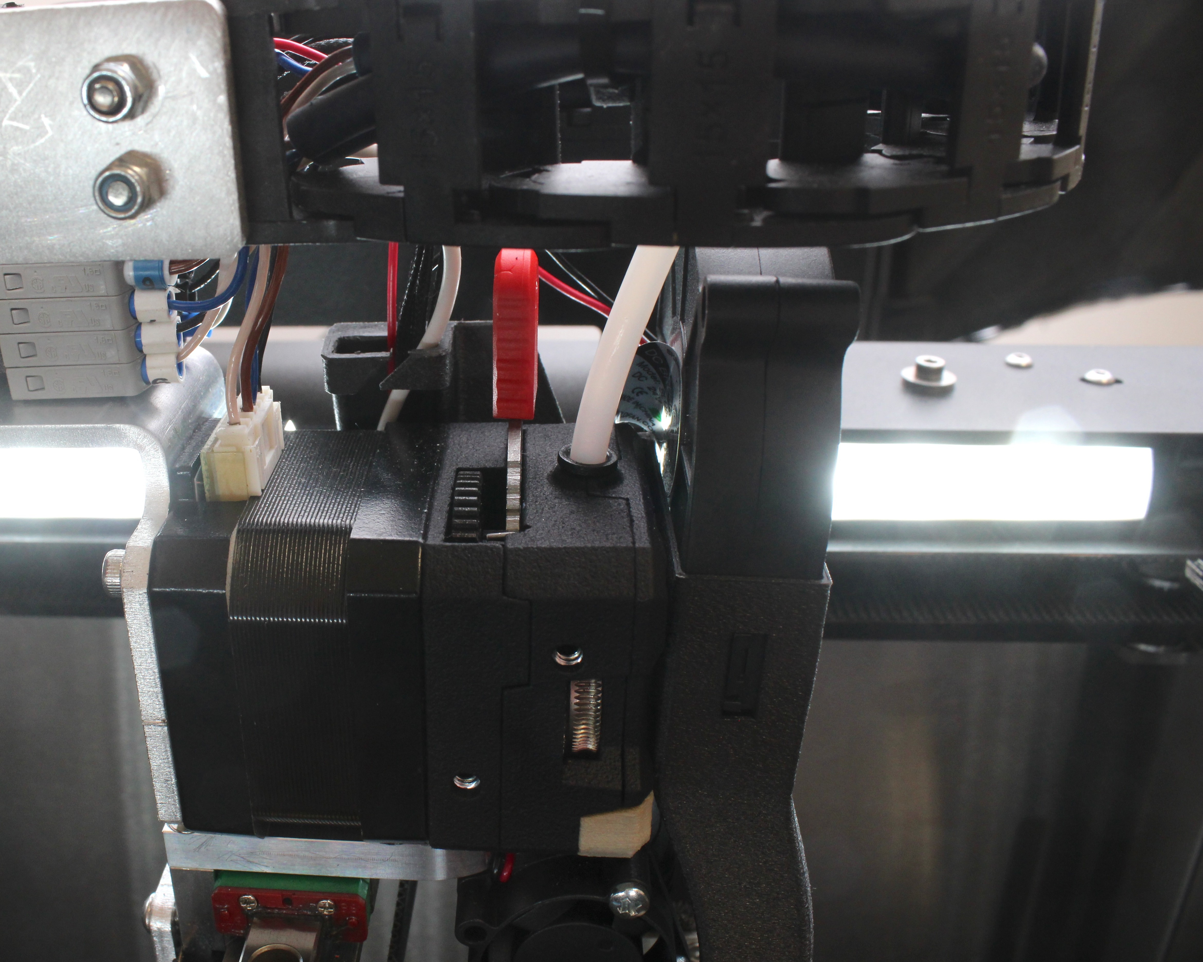
- Press the push-fit clip down toward the extruder and pull the tube straight up. The tube should release with upward force.
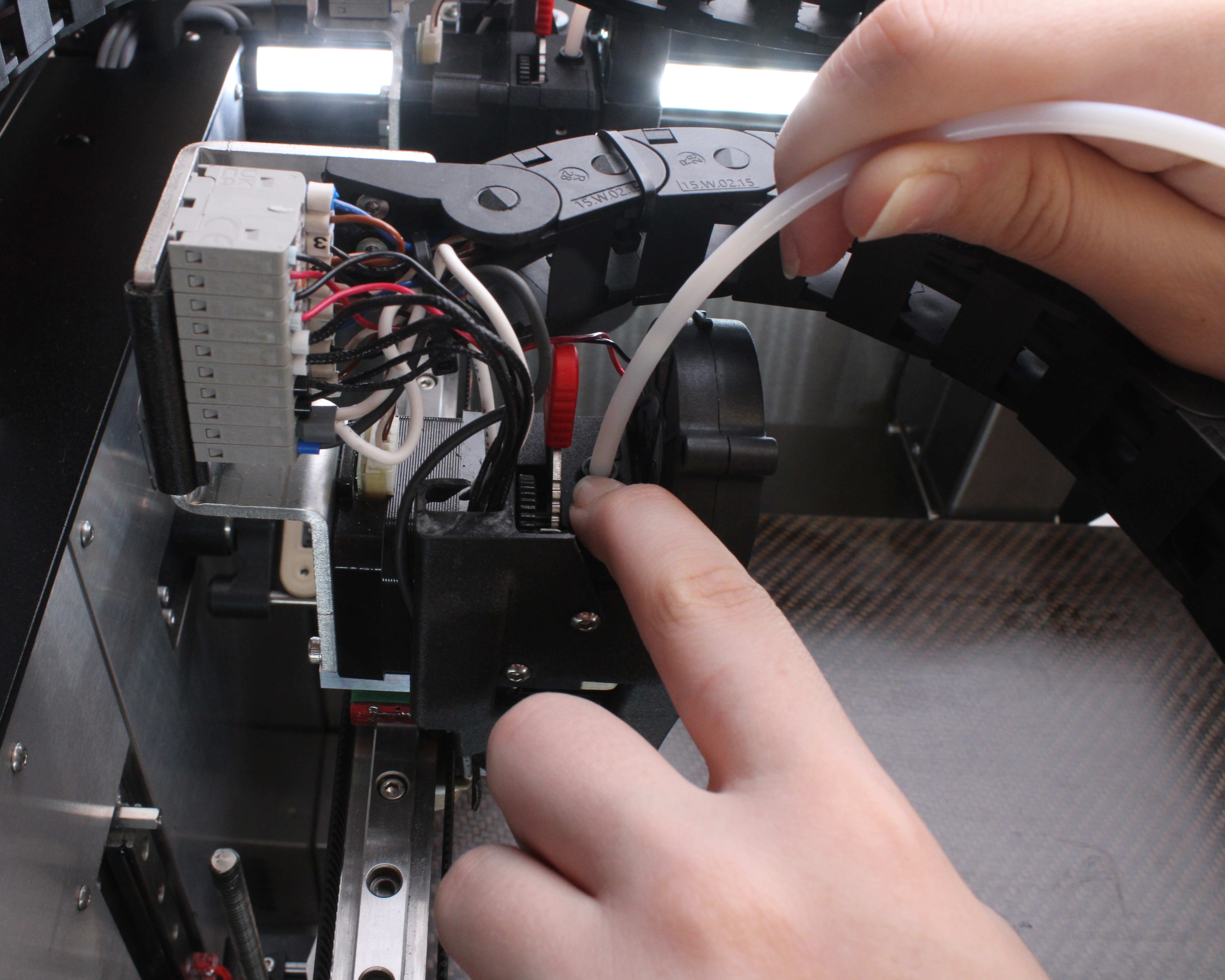
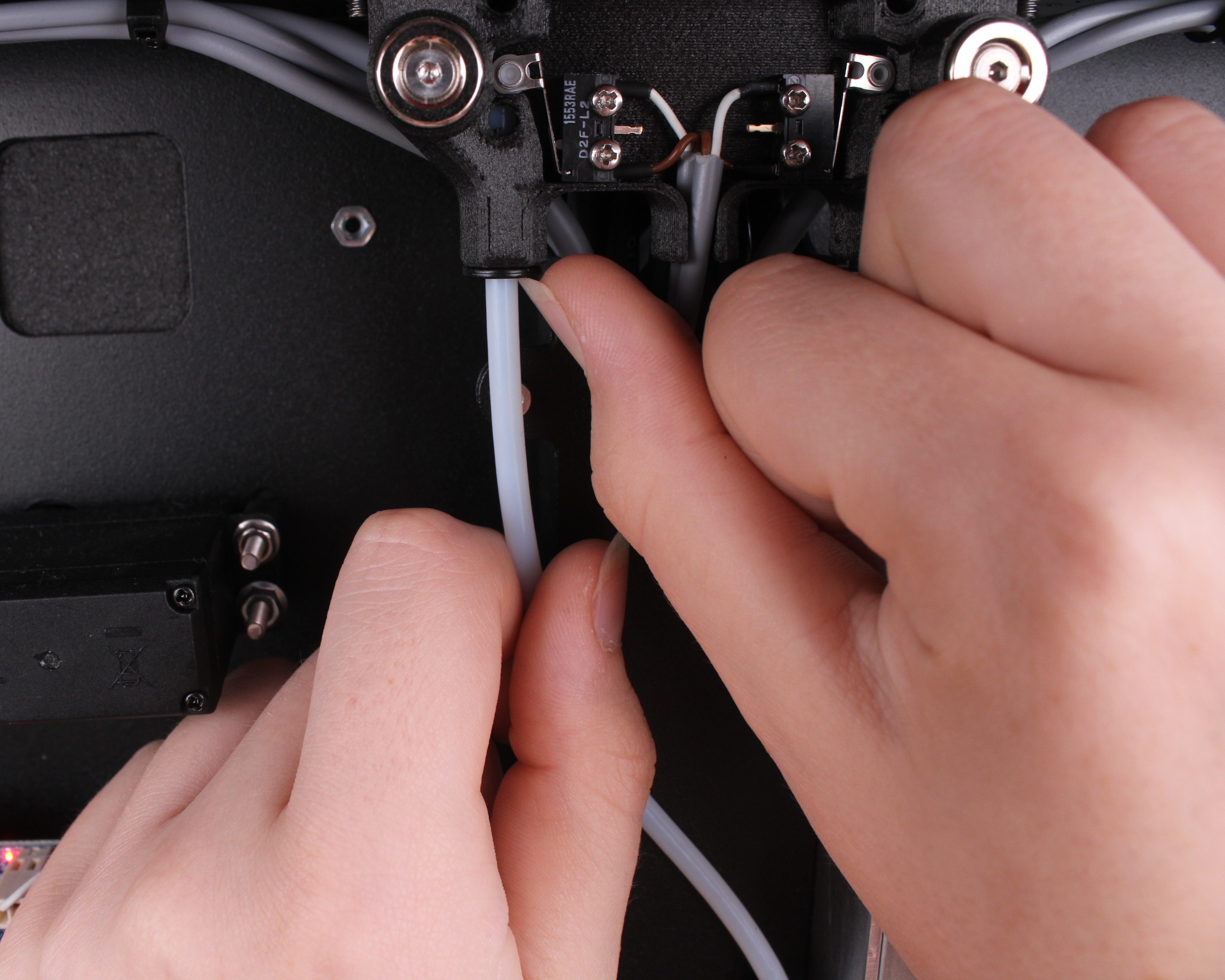
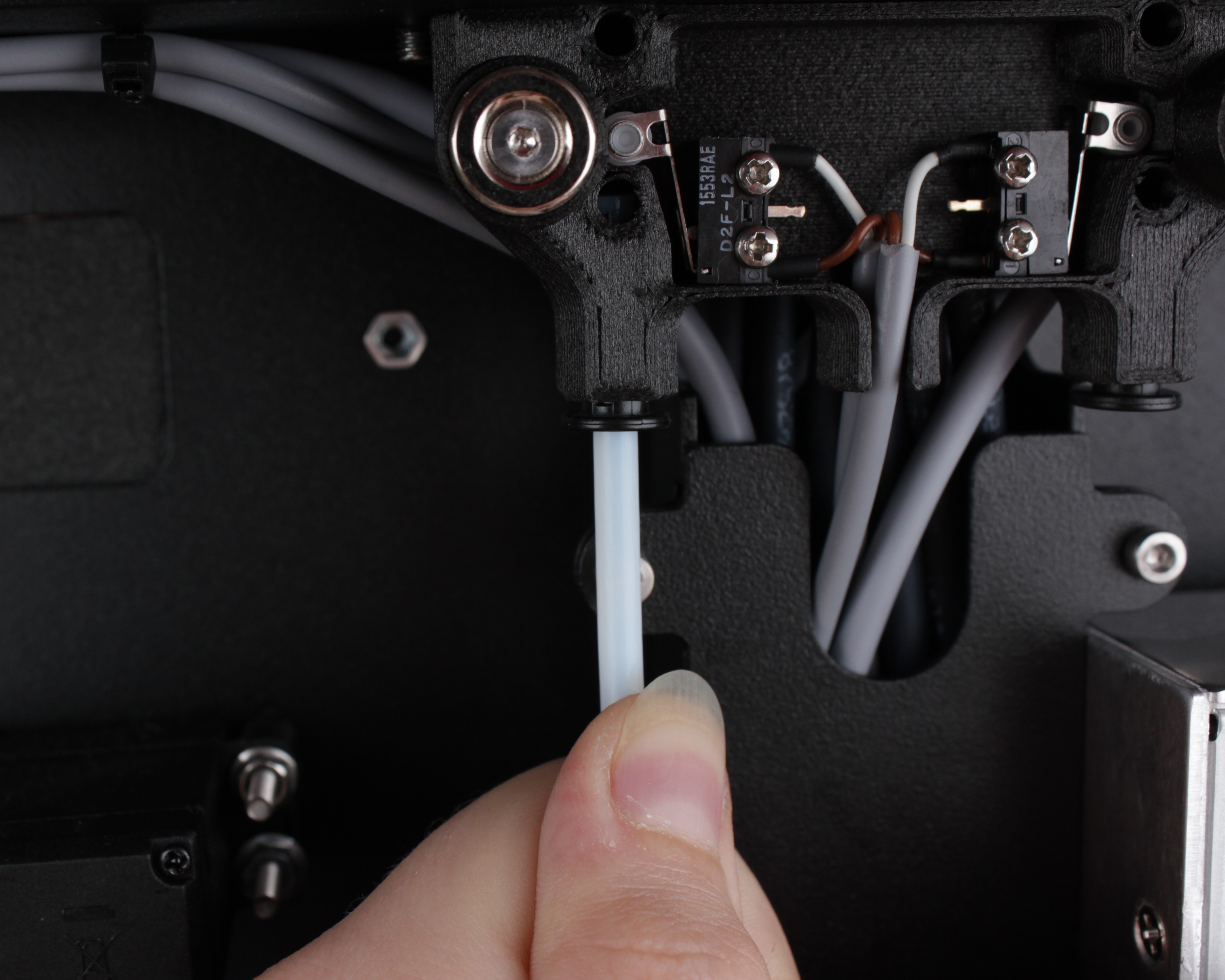
- At the other end, locate where the tube connects to the filament sensor mount in the upper portal. There is the same type of push-fit clip.
- Press the push-fit clip down and pull the tube up to disconnect it from the sensor housing.
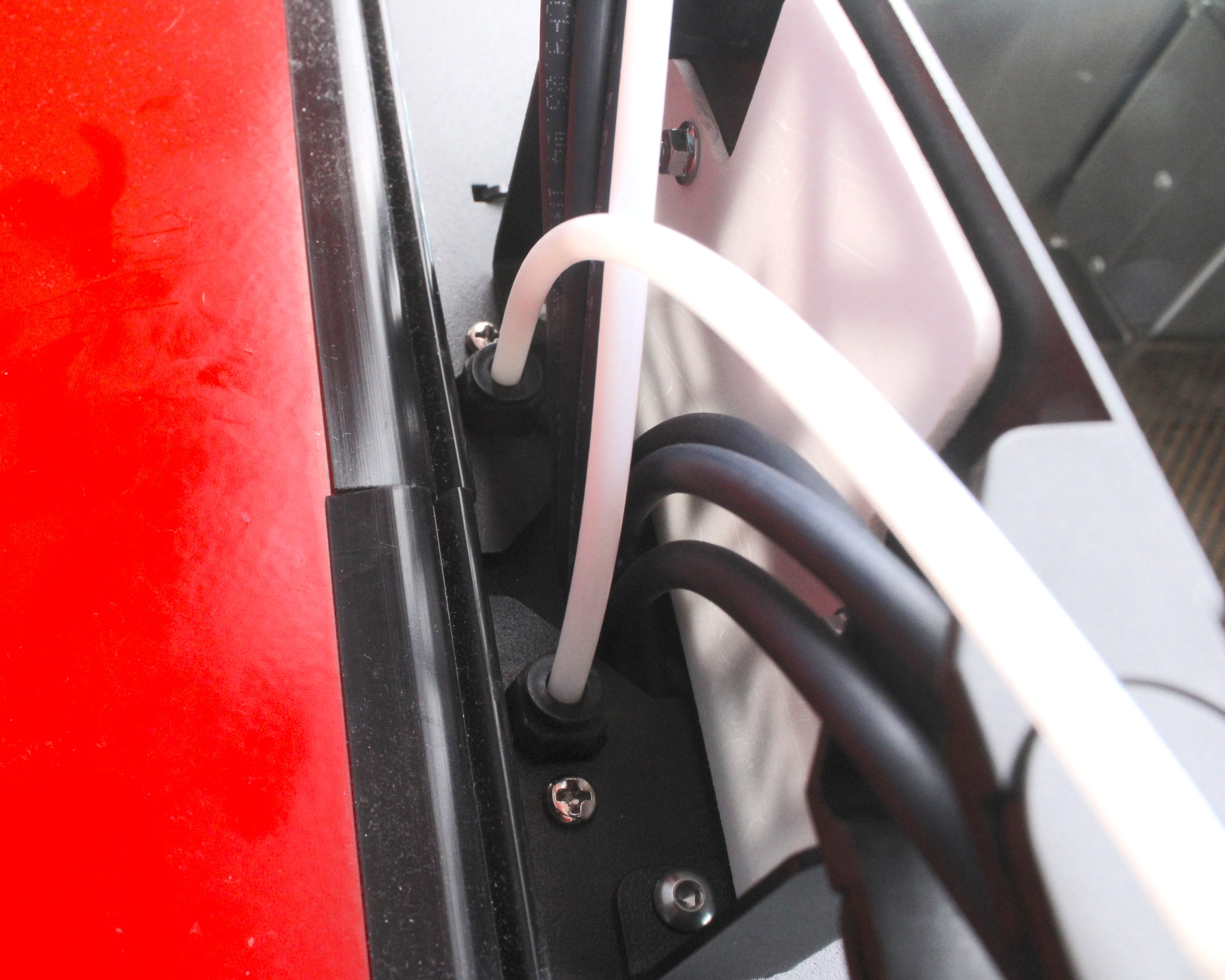
- Pull the old tube out of the clips/zip ties on the cable chain. Note the routing path – the new tube must follow the same route.
- Route the new tube through the cable chain clips following the same path as the old tube.
-
Push the new tube into the sensor mount connector with firm pressure. After inserting, gently tug the tube back – if it holds and does not come out, it is installed correctly.
-
Push the other end of the new tube into the extruder connector with firm pressure. Gently tug back to verify it is secured.
-
Load filament and verify it feeds smoothly through the new tube without resistance.
Replacing the Rear Tube (Rear Wall to Sensor)
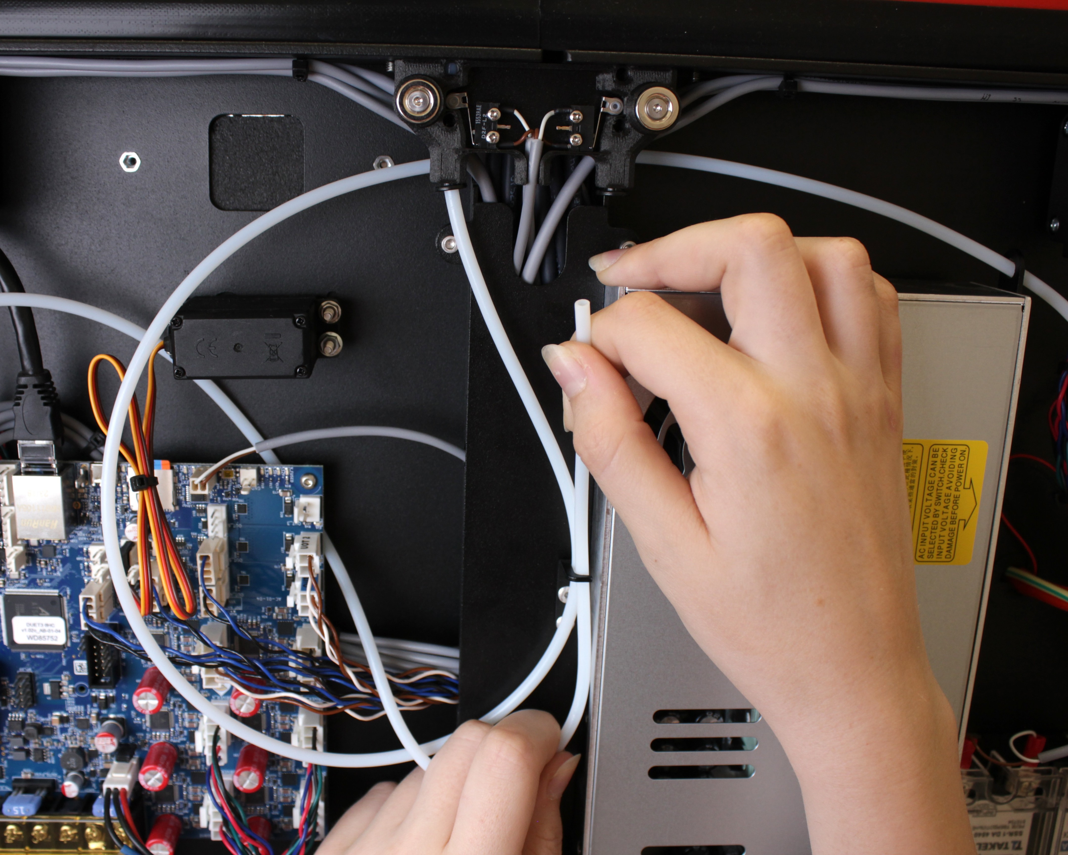
The rear tube runs from the rear wall filament entry through the electronics bay to the filament sensor in the upper portal. This tube wears less frequently, but it can compress if a tangled spool pulls back on the filament.
The rear tubes have different lengths for T0 and T1. T0 has a longer path, so the tube is longer; T1 is shorter. Make sure you have the correct tube for the corresponding tool.
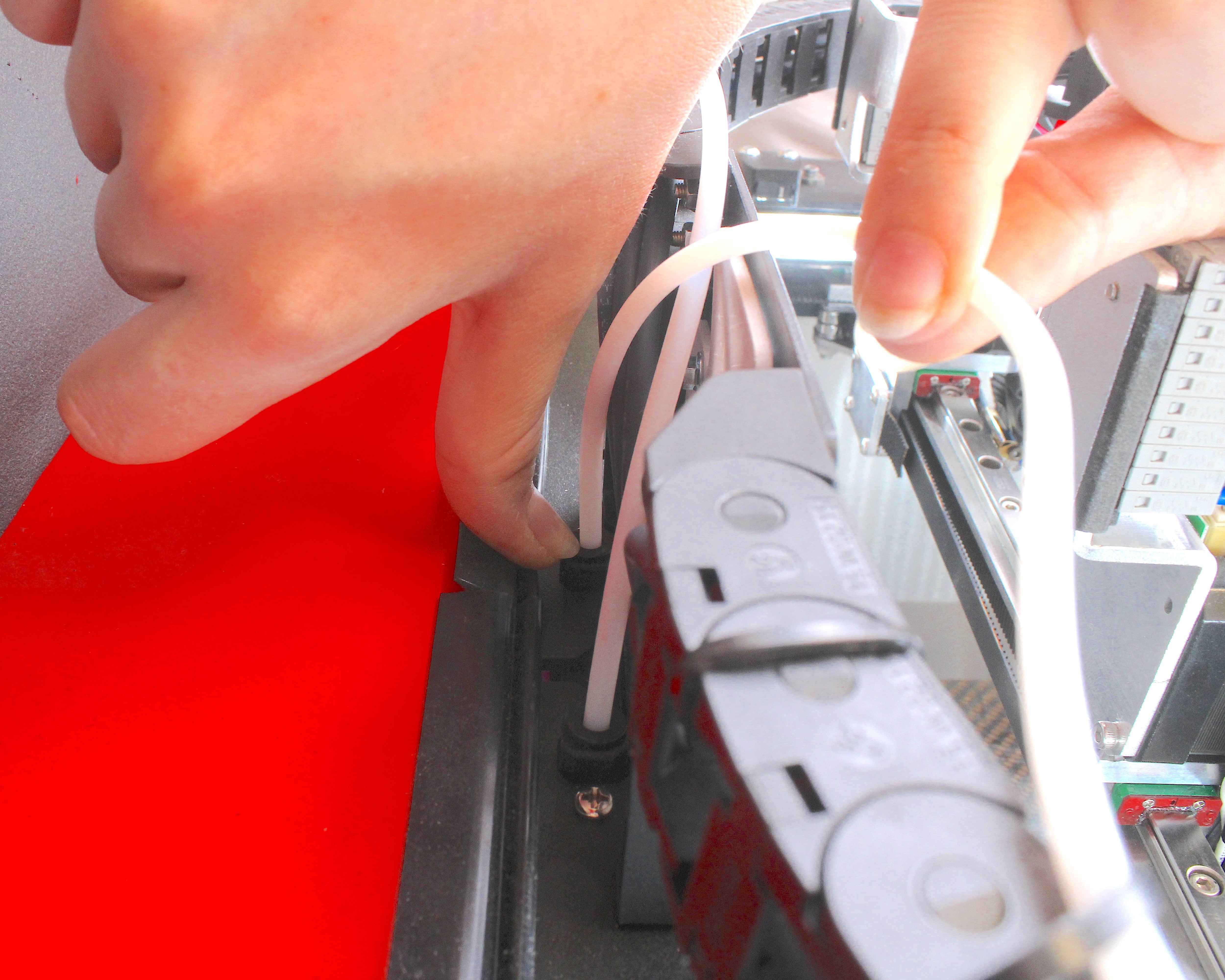
- At the rear wall, locate the push-fit clip on the filament entry point. Press the clip down and pull the tube toward you (away from the printer) to disconnect it.
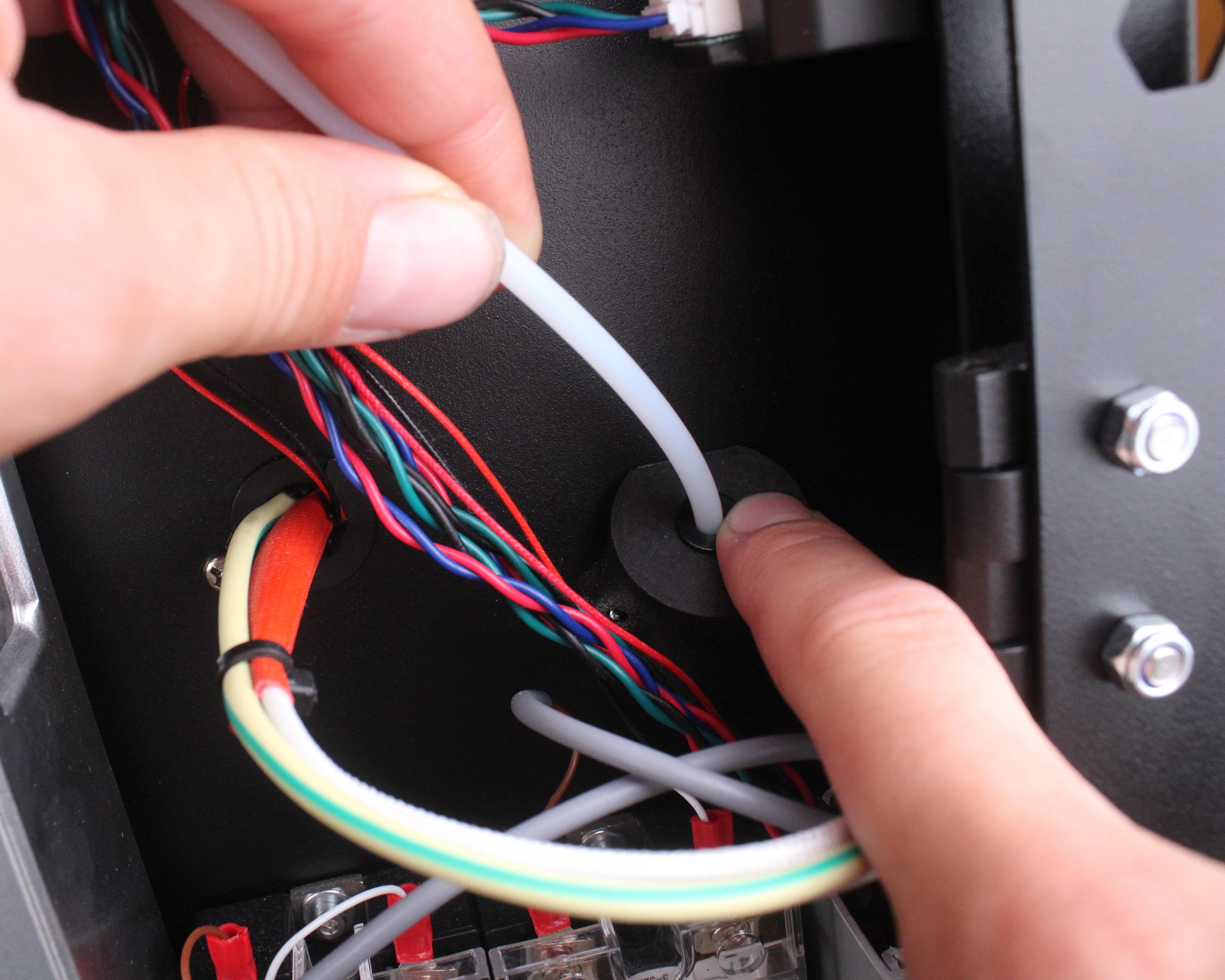
- At the upper portal end, press the push-fit clip up and pull the tube down to disconnect it from the sensor mount.
- Pull the old tube out of any holders or clips in the rear compartment. Note the routing path.
-
Route the new tube through the same path and holders.
-
Push the tube into the sensor mount connector with firm pressure. Gently tug back to verify it holds.
-
Push the other end into the rear wall connector with firm pressure. Tug back to confirm it is secured.
-
Load filament and verify smooth feeding.
Rerouting Tubes for Stiff Filament
If you are printing with very rigid filament (carbon-filled, glass-filled, or high-temperature materials), the sharp bends in the rear tube path can cause filament to crack or break inside the tube. In this case, consider rerouting the rear PTFE tubes to follow gentler curves.
For detailed instructions on rerouting, see the Filament Breaks in Tube – Troubleshooting Guide.
FAQ
Troubleshooting
Support
If you could not find an answer here, reach out to our support team.