HEPA Fan
This guide covers replacing the Rev 2 HEPA filter fan on the Vision Miner 22IDEX V4 only for printers with serial number 296 or higher. The fan is mounted behind the HEPA filter inside the enclosure on the right side (when facing the front of the printer). It pulls chamber air through the HEPA filter during printing. Replace the fan if it is noisy, vibrating, not spinning, or fails the HEPA Fan Test macro.
Before you begin - safety and risk
Read the Safety - Before You Begin article to understand the hazards involved in working on the Vision Miner 22IDEX V4 – including electrical, thermal, mechanical, and chemical risks. All procedures in this wiki are provided as recommendations only. By choosing to follow any procedure, you do so at your own risk.
This article replaces the fan only
To replace the HEPA filter element itself, see HEPA Filter Replacement.
Serial number 296 or higher – this guide only
Check the serial number on the sticker on the back of your printer. If the serial number is 295 or lower, do not use this guide – the Rev 1 fan and related hardware differ from the steps and photos here. If the serial number is 296 or higher, this procedure applies and you need the Rev 2 spare. If you are unsure which machine you have, contact our support team.
Tools and Materials
- 2.5 mm Hex screwdriver (hex wrench)
- 2 mm Hex screwdriver (hex wrench) – only needed if your machine has the older 2 mm button head housing screws
- 5.5 mm Wrench (or socket)
- Threadlocker (we recommend Loctite 243)
- HEPA Filter Fan - Rev 2 – replacement fan for serial number 296 and above (required for this guide)
1. Preparation
1. Home the printer and raise the build plate.
Home the machine if it is not already homed, then raise the build plate so there is clear working space inside the enclosure – the bed should sit about 10 mm below the nozzle.
2. Turn off the printer and unplug it from the power outlet.
Wait at least 60 seconds after powering off
Wait at least 60 seconds after powering off for the capacitors to discharge before touching any internal components.
3. Wait at least 60 seconds for the capacitors to discharge.
2. Removing the stainless steel housing
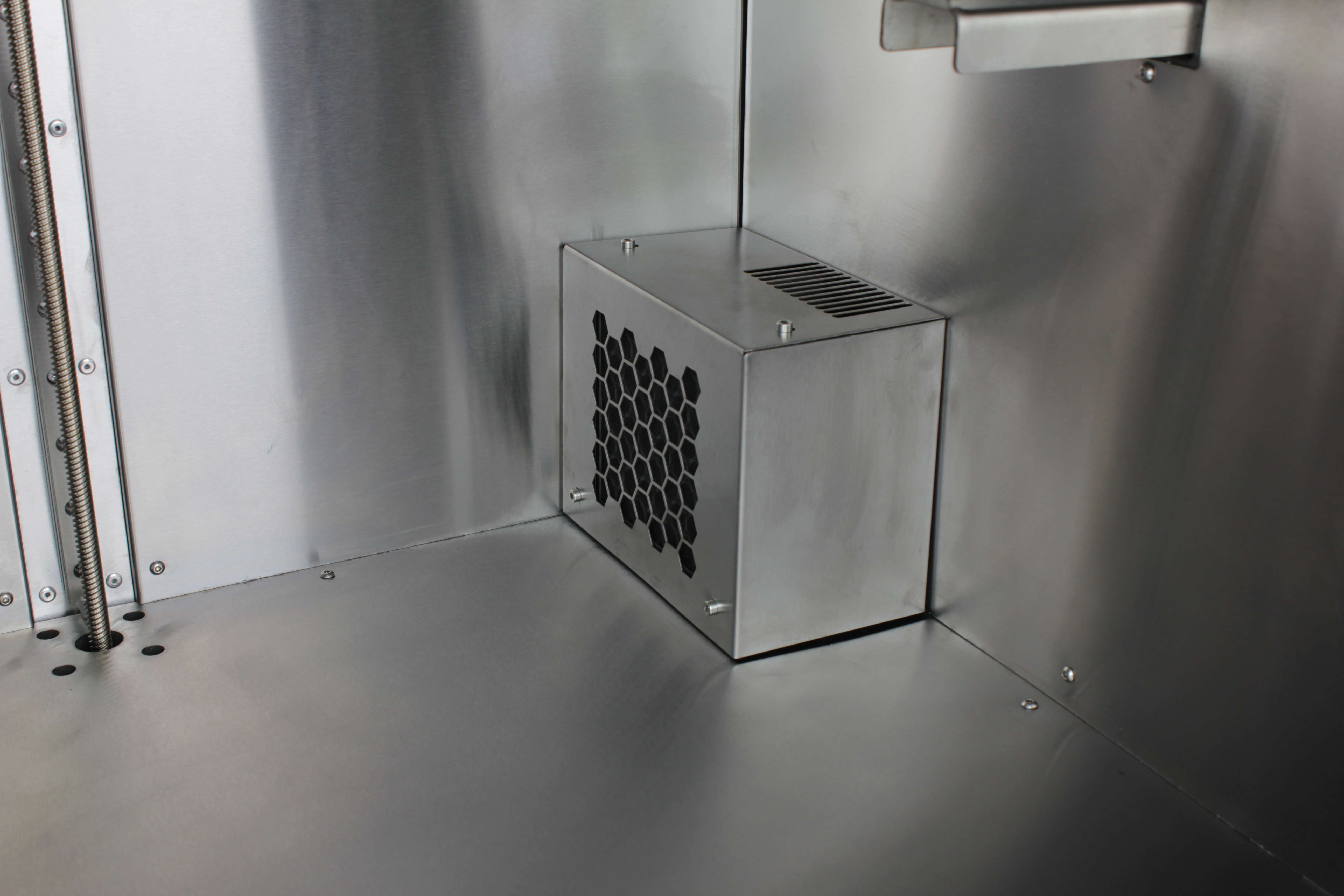
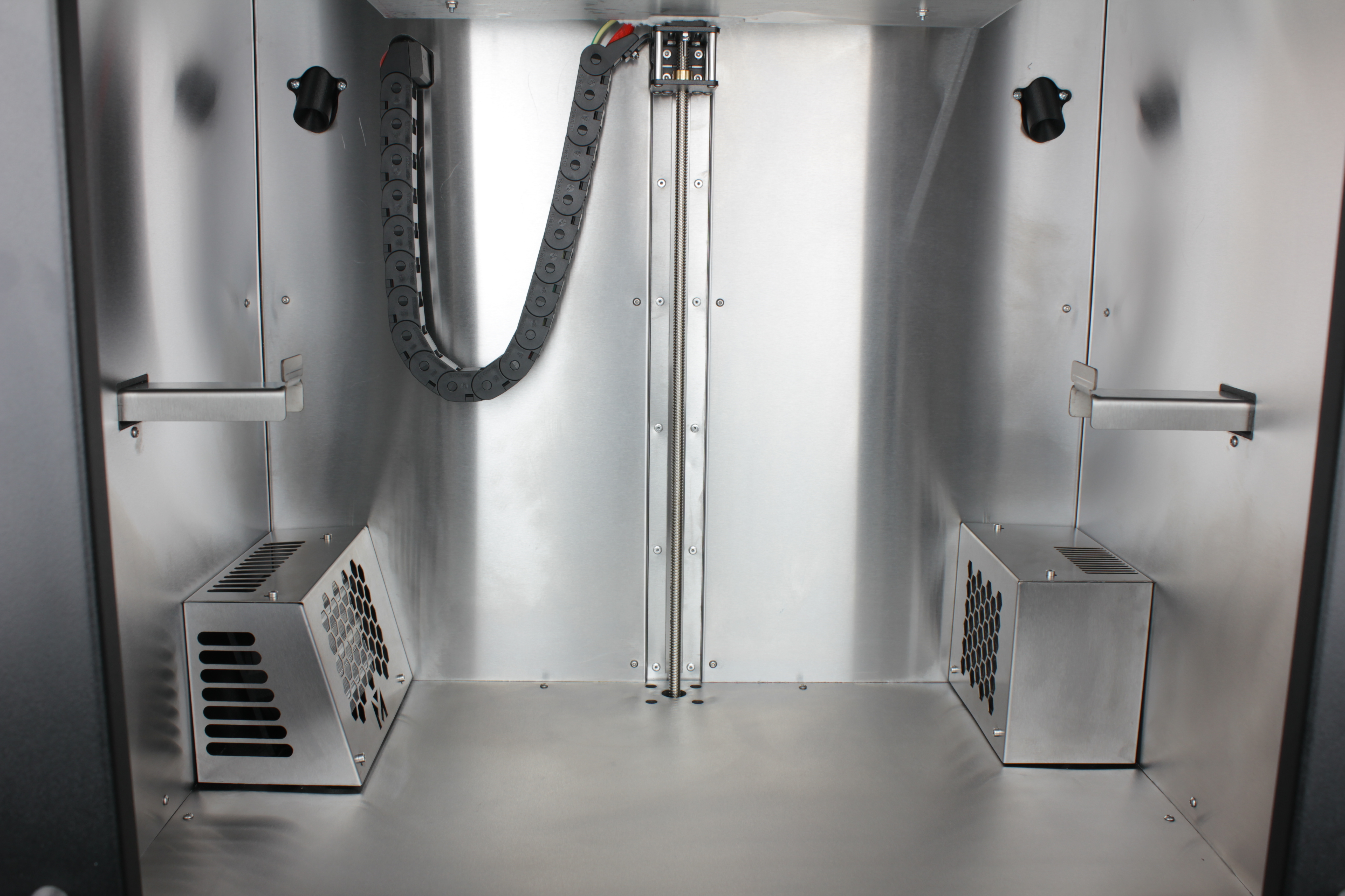
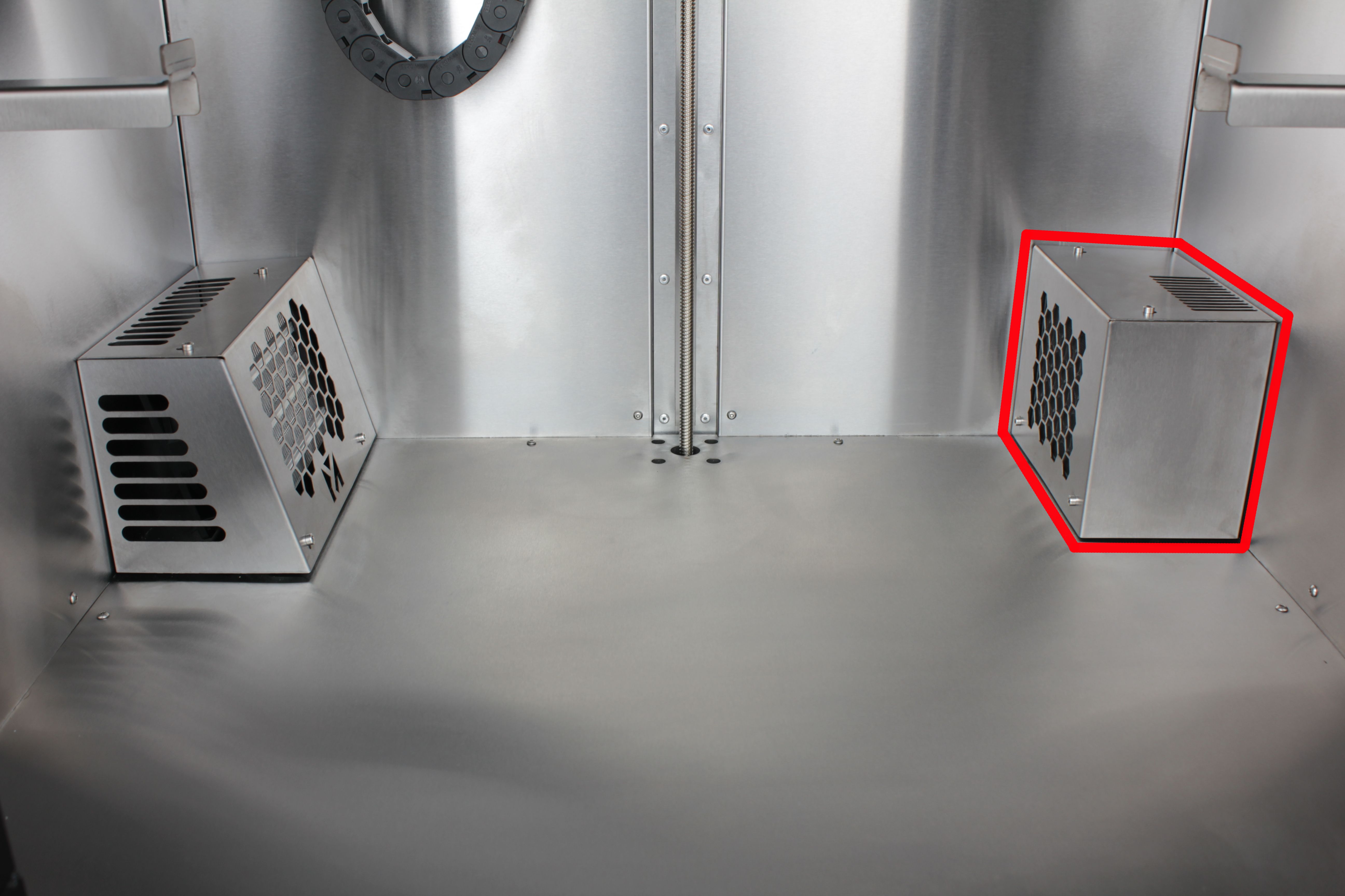
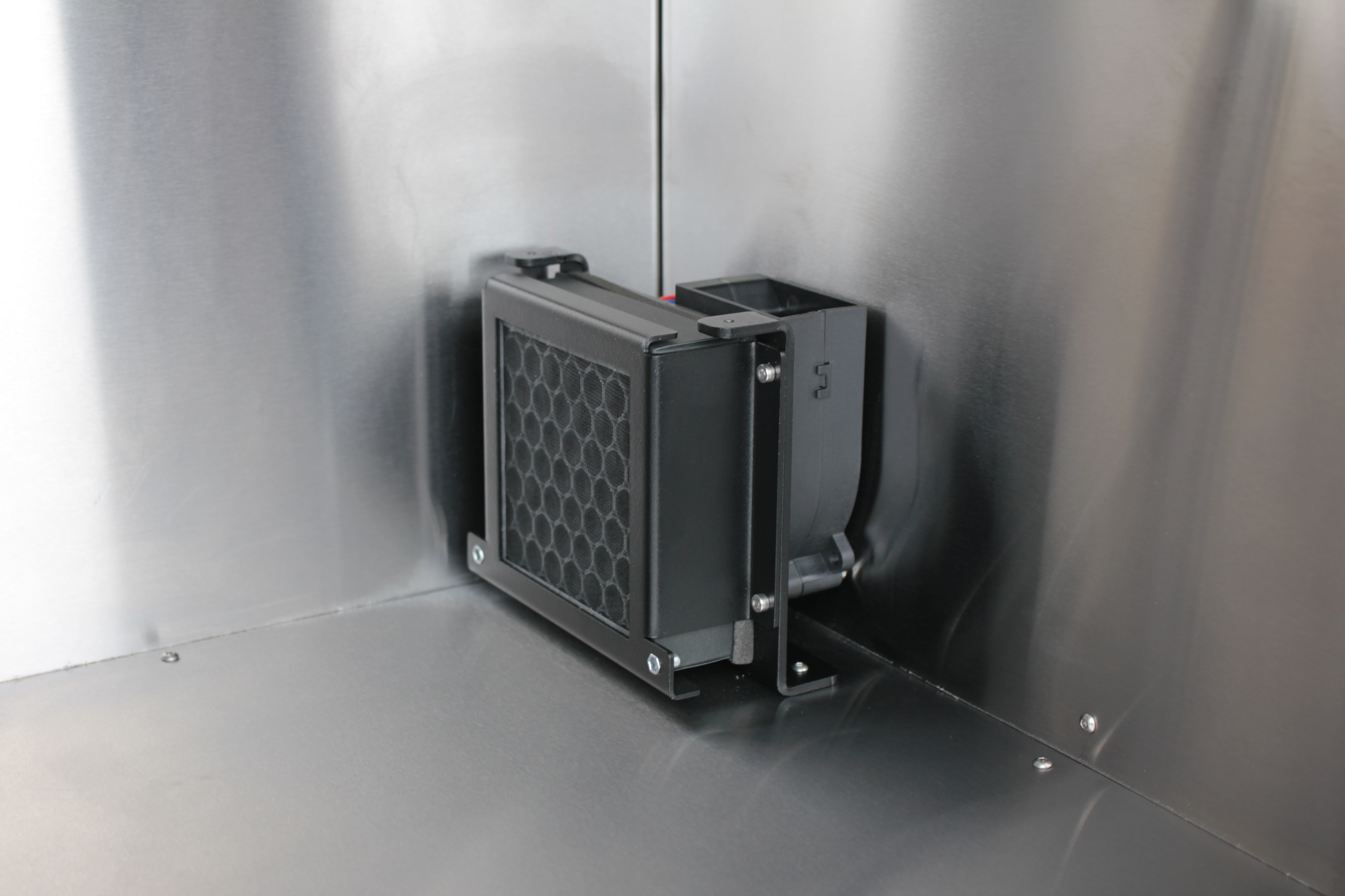
4. Look inside the enclosure.
On the right side (when facing the front) you will see a rectangular protrusion – the HEPA filter assembly. The left protrusion is the chamber heater; do not touch it.
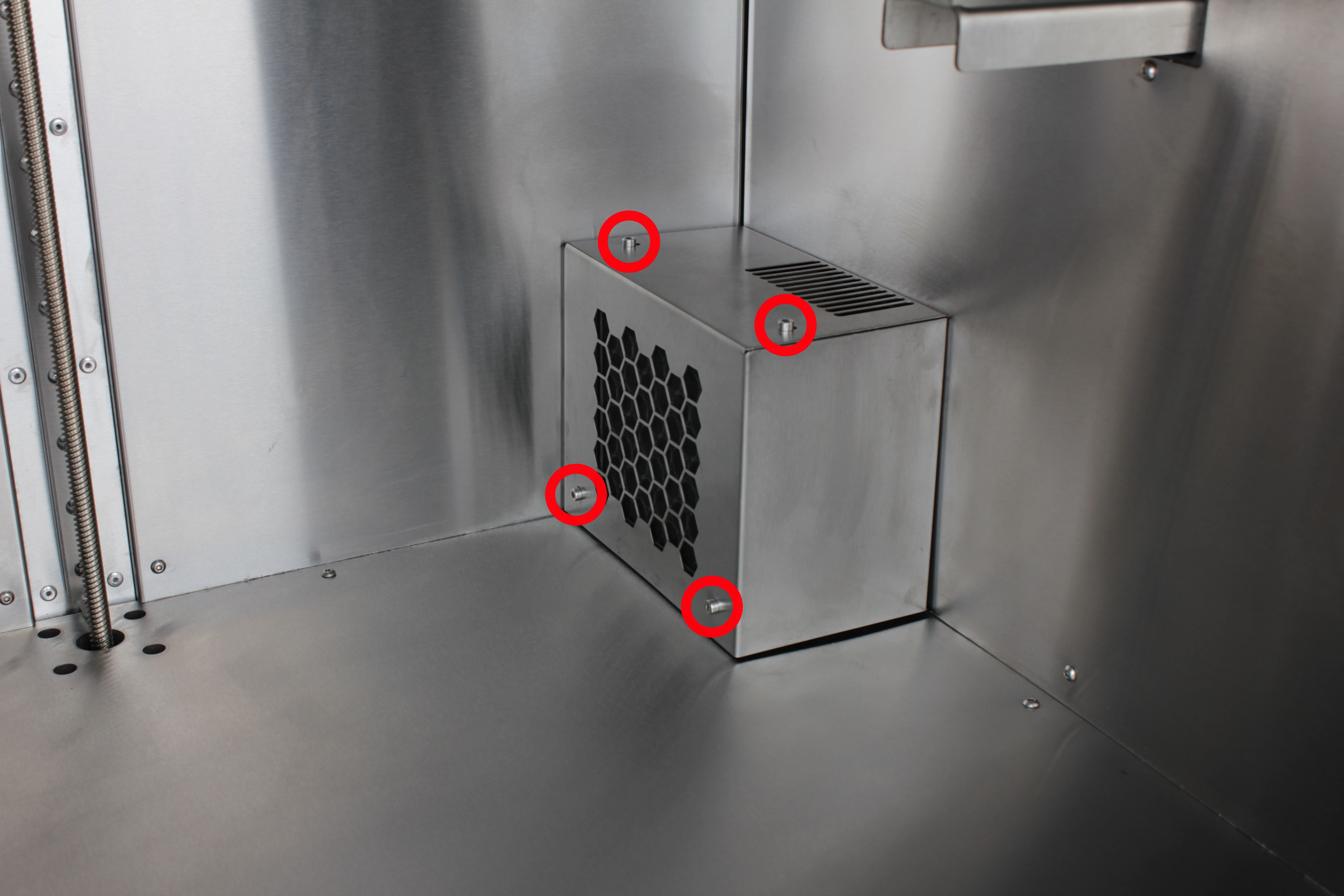
5. Unscrew the four screws holding the stainless steel housing.
Use a 2.5 mm hex screwdriver.
2 mm housing screws strip easily
Older machines use 2 mm button head screws for the housing. These are easy to strip because of the threadlocker on the threads – insert the hex screwdriver fully and keep it straight. We recommend replacing them with socket head cap screws of the same length that take a 2.5 mm hex.
6. Remove the stainless steel housing and set it aside.
3. Disconnecting the HEPA fan cable
Disconnect the fan cable and remove the grommet before the bracket
Disconnect the fan cable and remove the cable grommet before unbolting the bracket. The fan cable connector is too large to fit through the enclosure wall hole with the grommet in place.
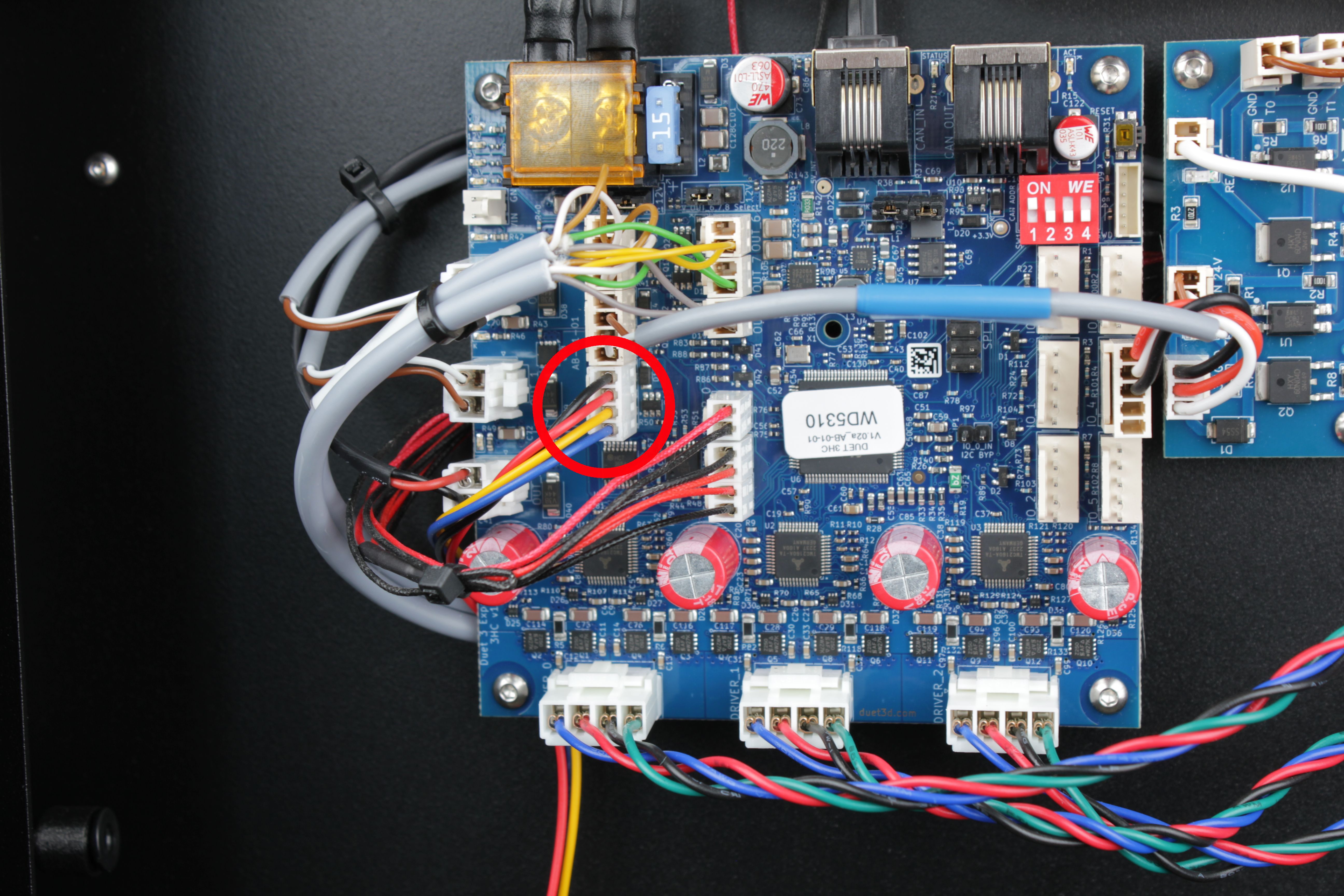
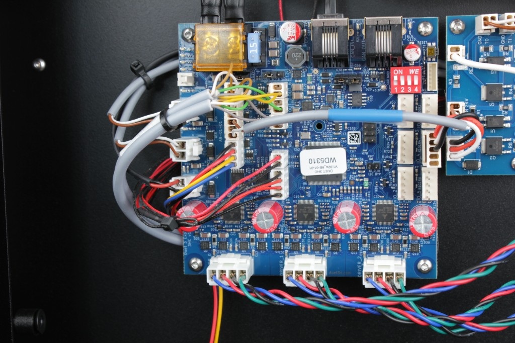
7. Go to the rear electronics bay.
Locate the HEPA fan cable connector on the expansion board and disconnect it.
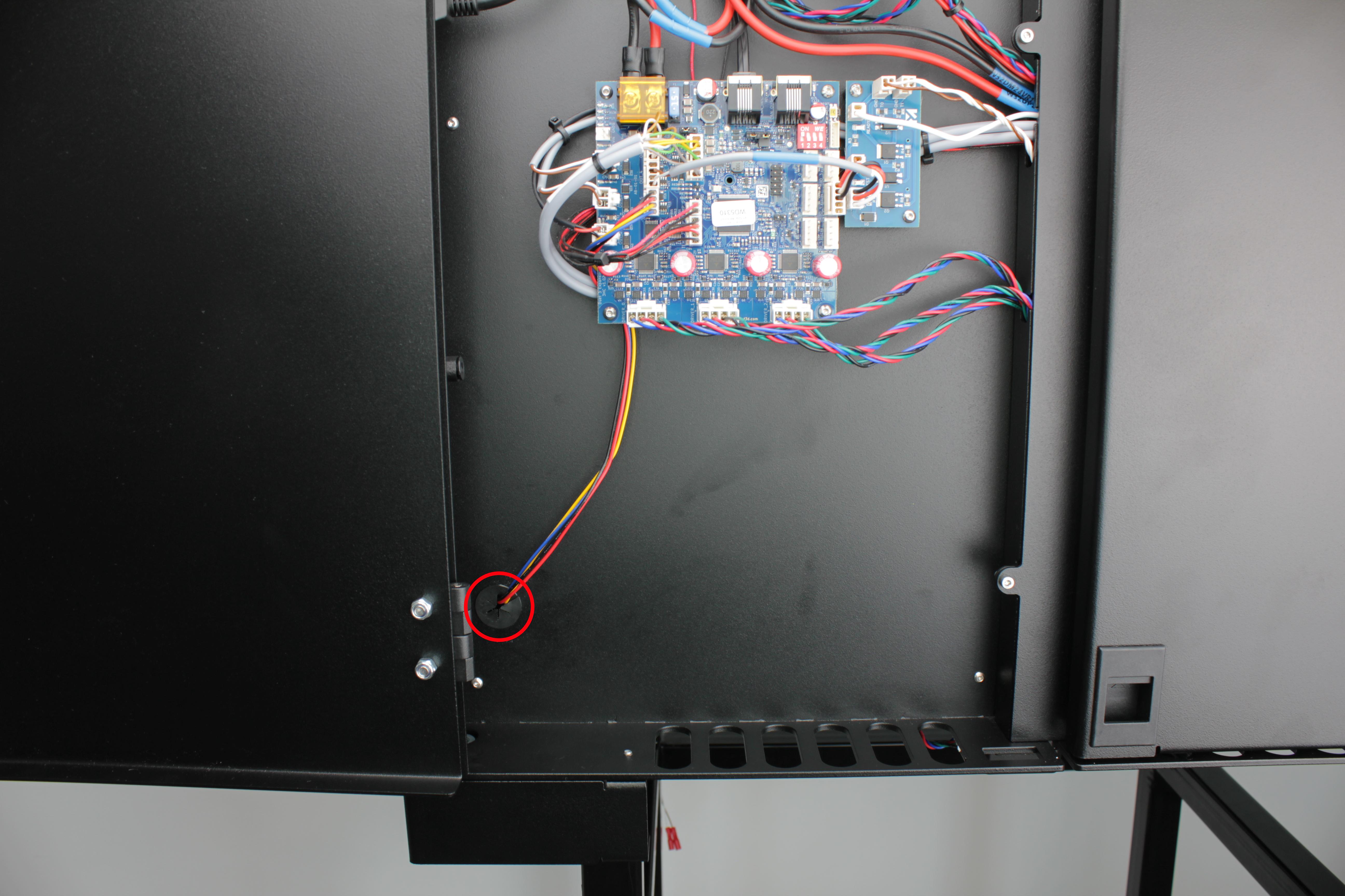
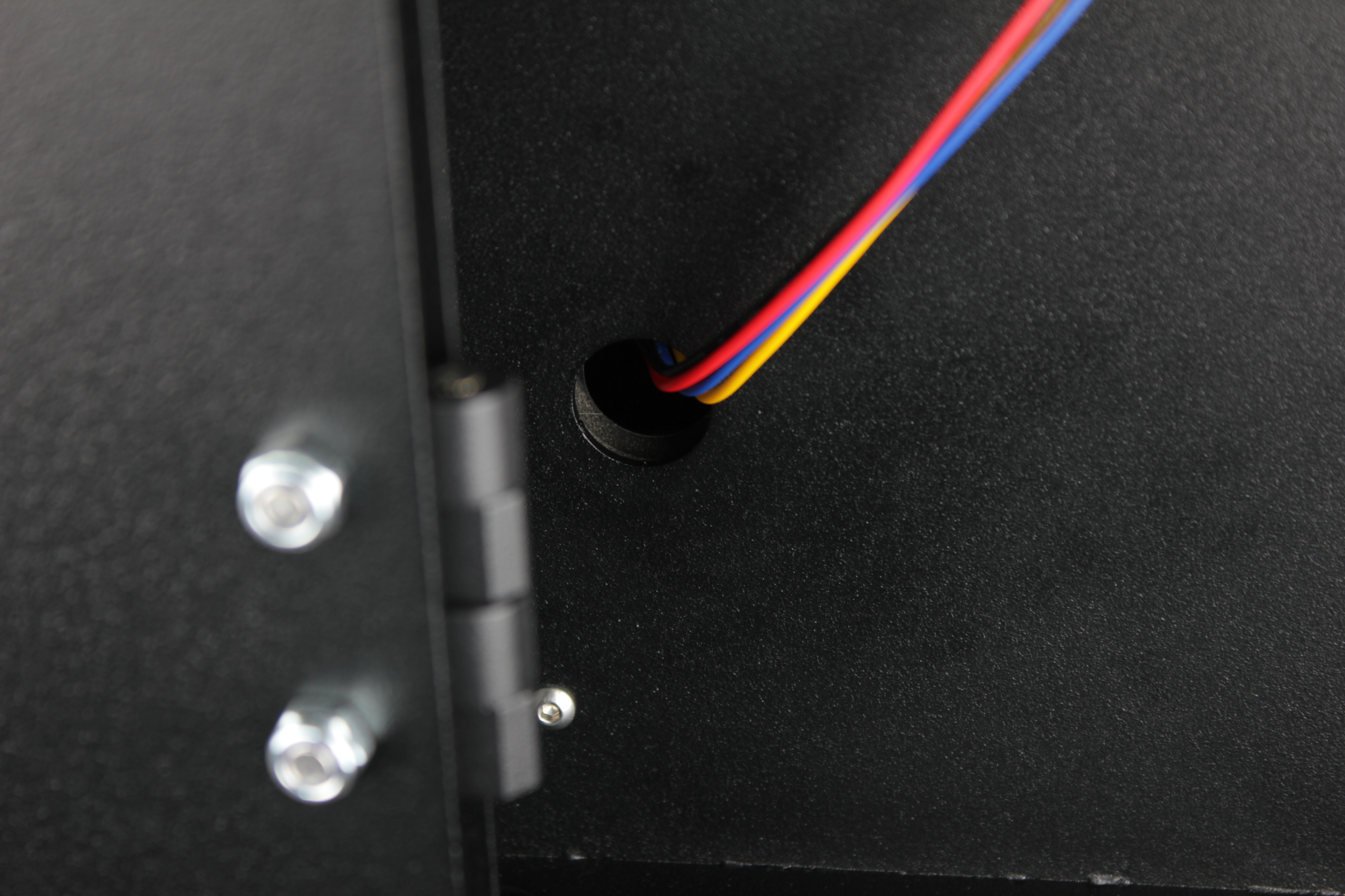
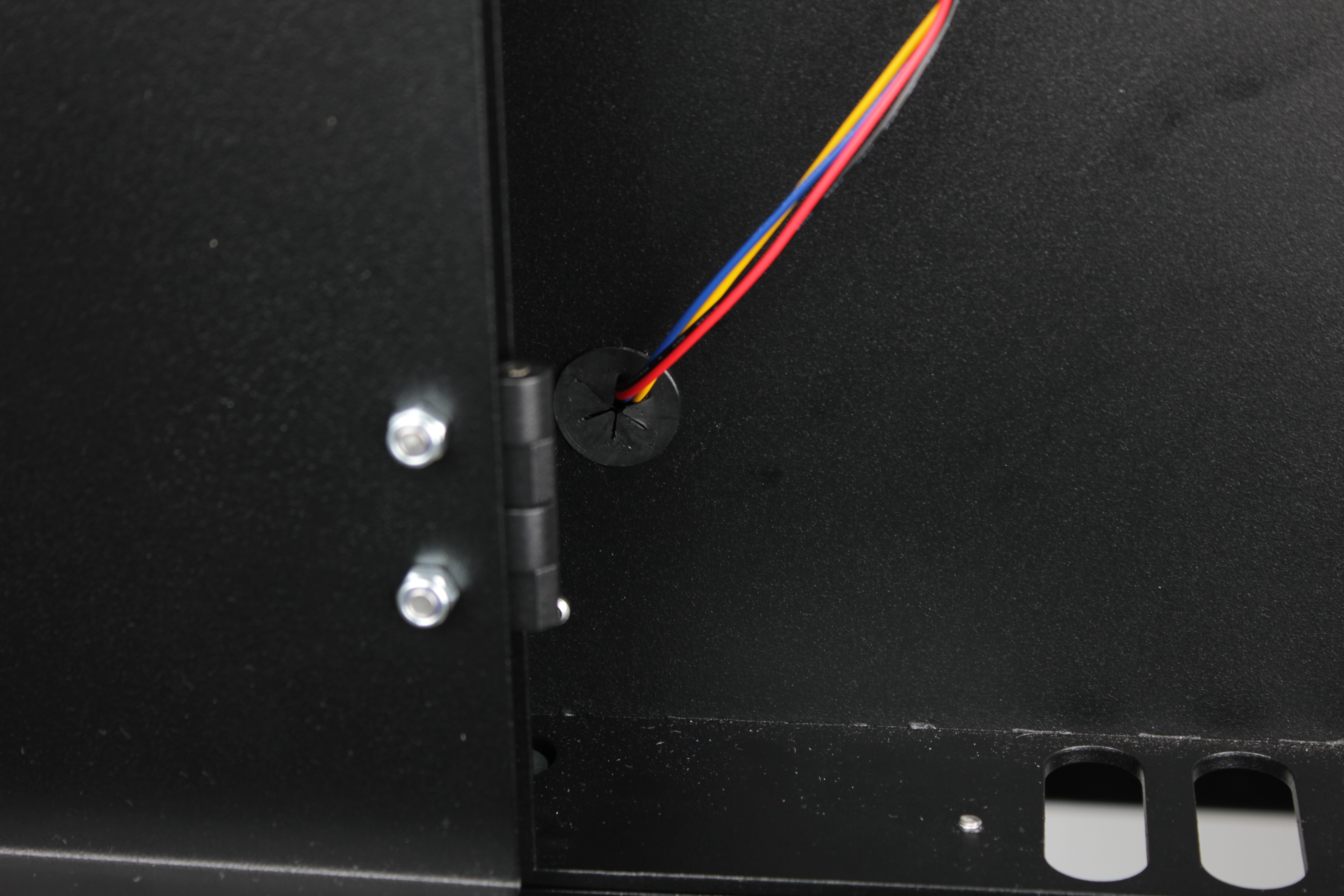
8. Locate the cable grommet on the enclosure wall.
From the electronics bay side, find the hole where the fan cable passes through. The hole is sealed with a grommet 3D-printed from TPU. The grommet has a slit on one side.
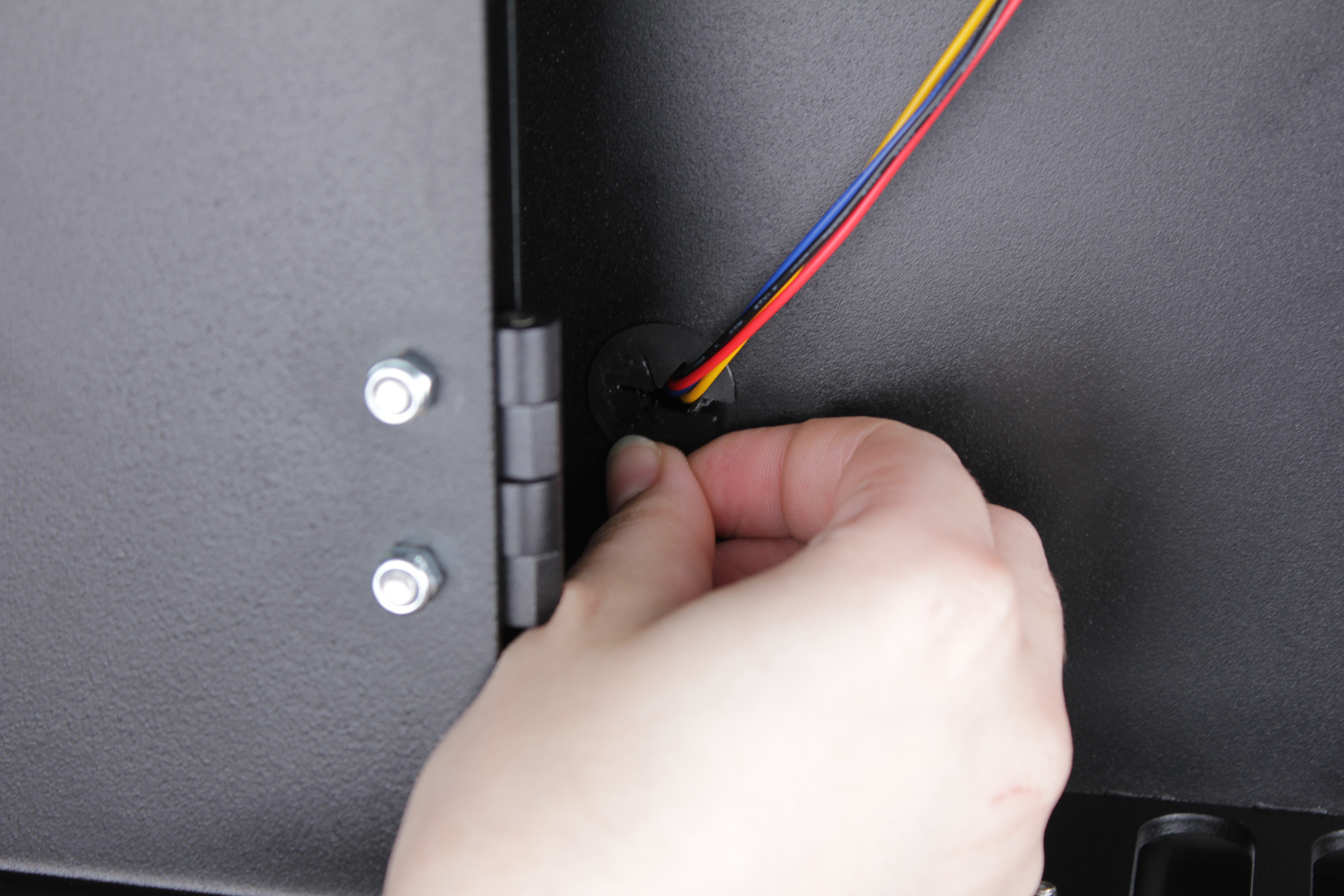
9. Pull the grommet out of the hole and slide it off the cable through the slit.
Set the grommet aside.
10. Pull the disconnected cable free from behind the expansion board so it has slack to move.
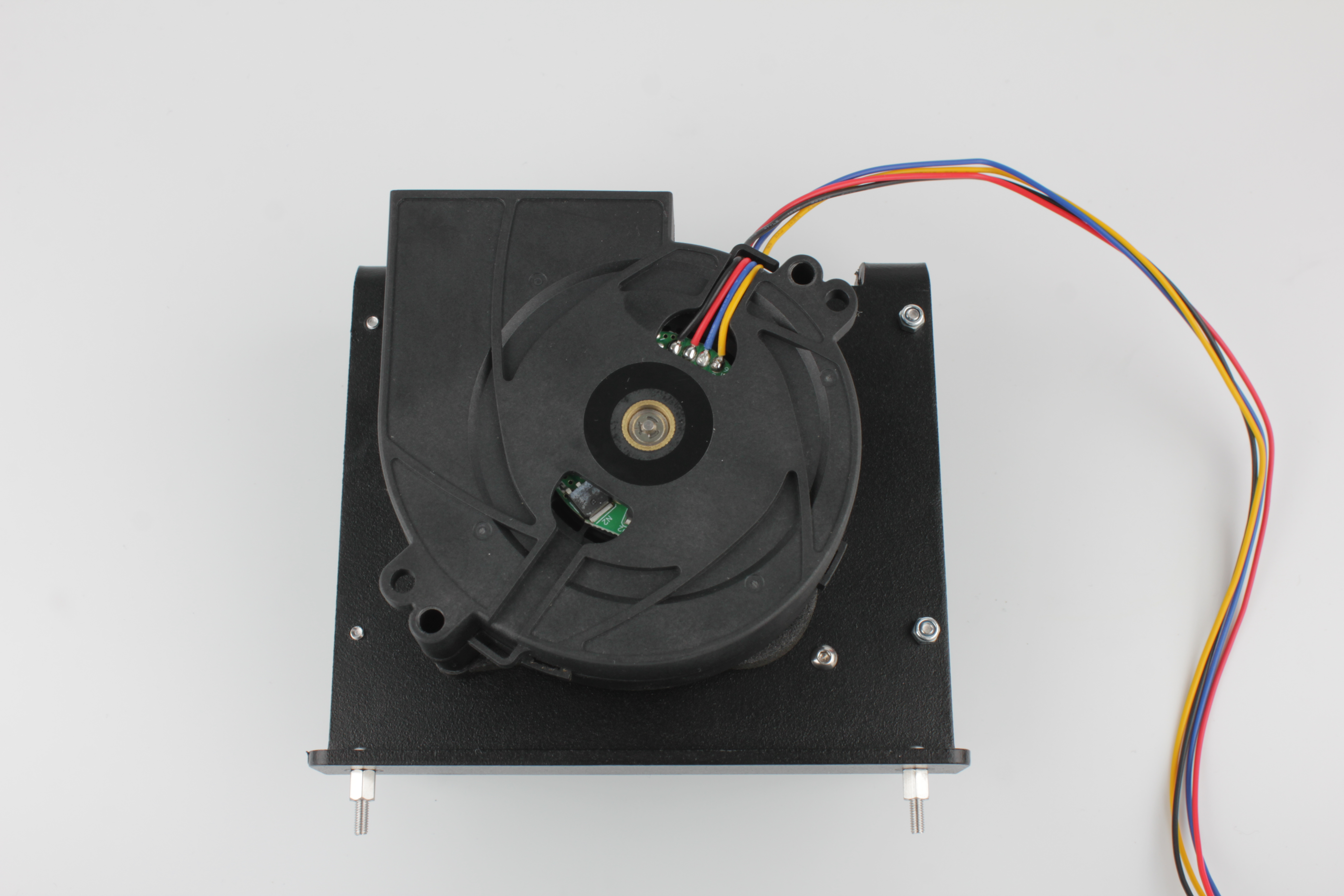
4. Removing the bracket assembly
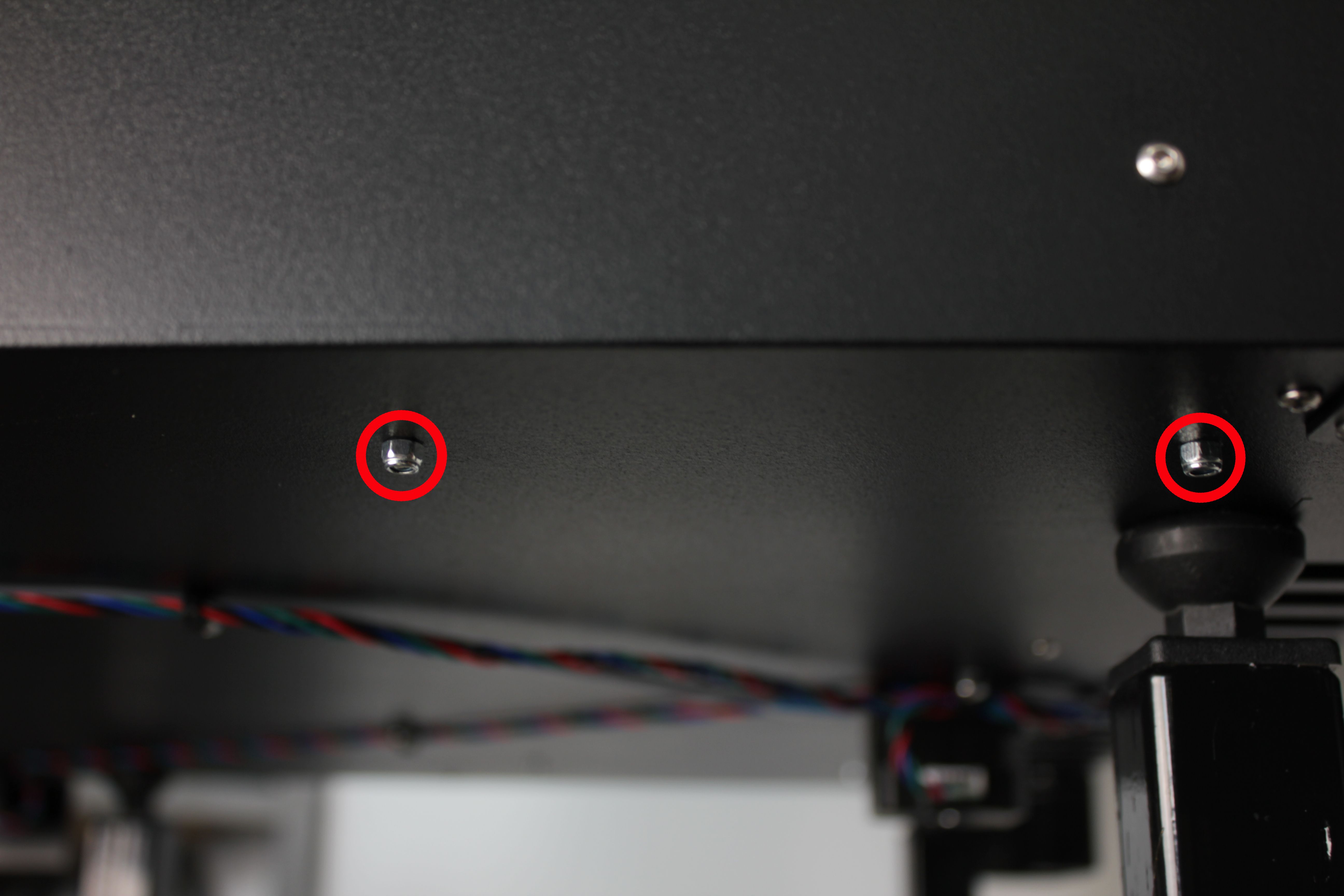
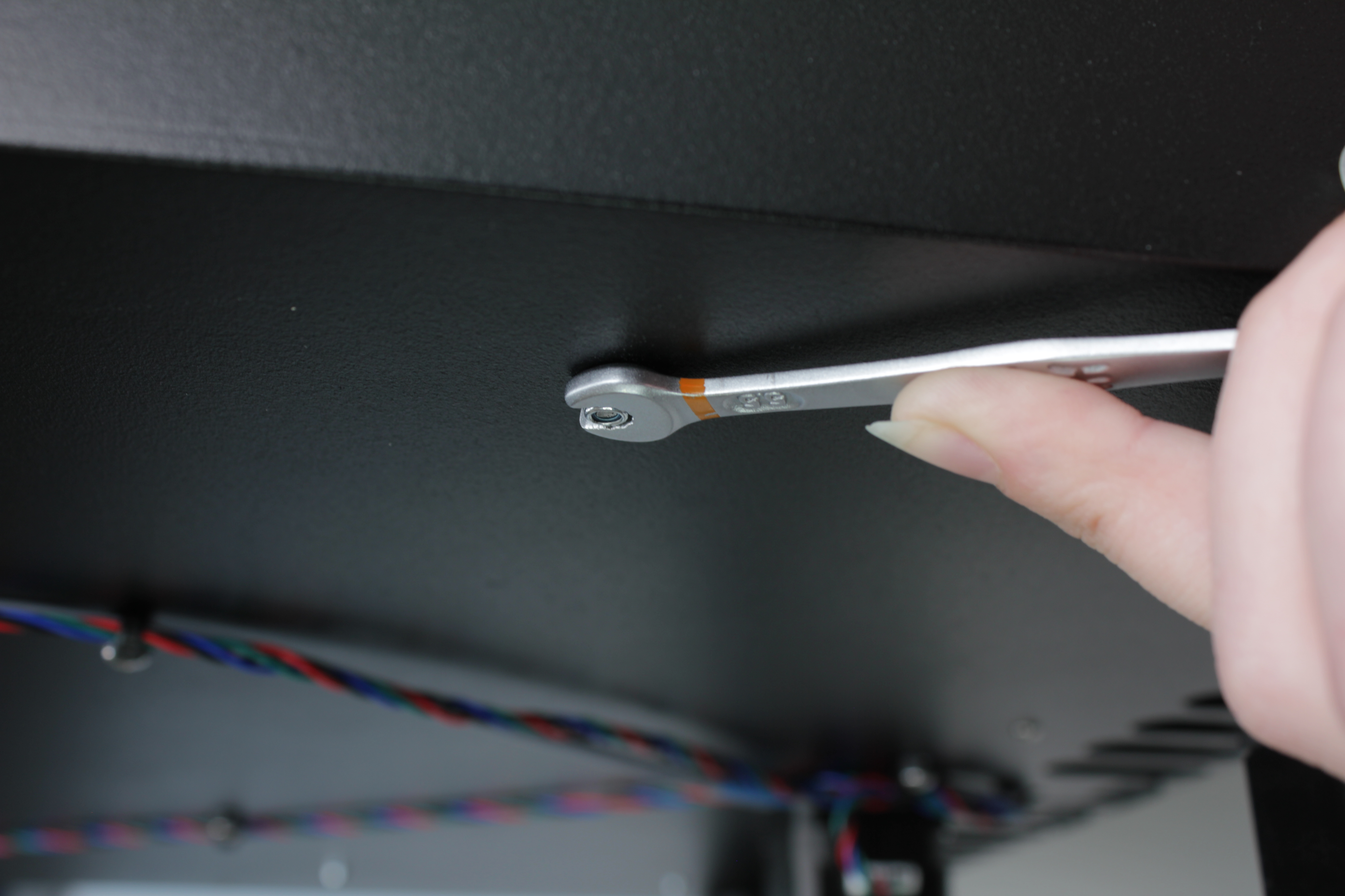
11. Unscrew the two M3 nuts that secure the HEPA filter bracket.
Turn the printer around and look at the outside bottom. Use a 5.5 mm wrench.
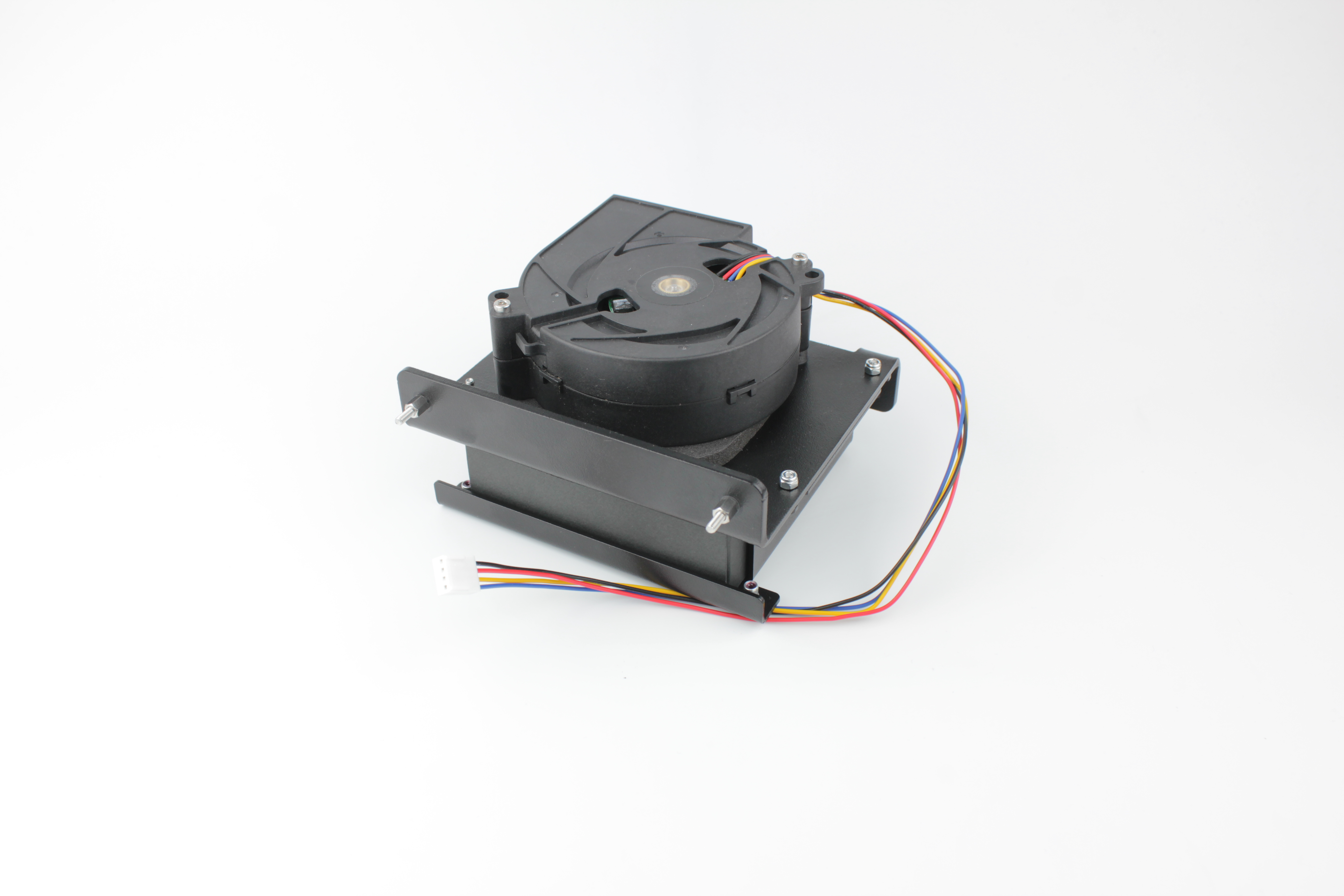
12. Pull the bracket assembly toward you.
The fan cable will slide through the wall hole as the assembly comes out. Place the assembly on a clean surface.
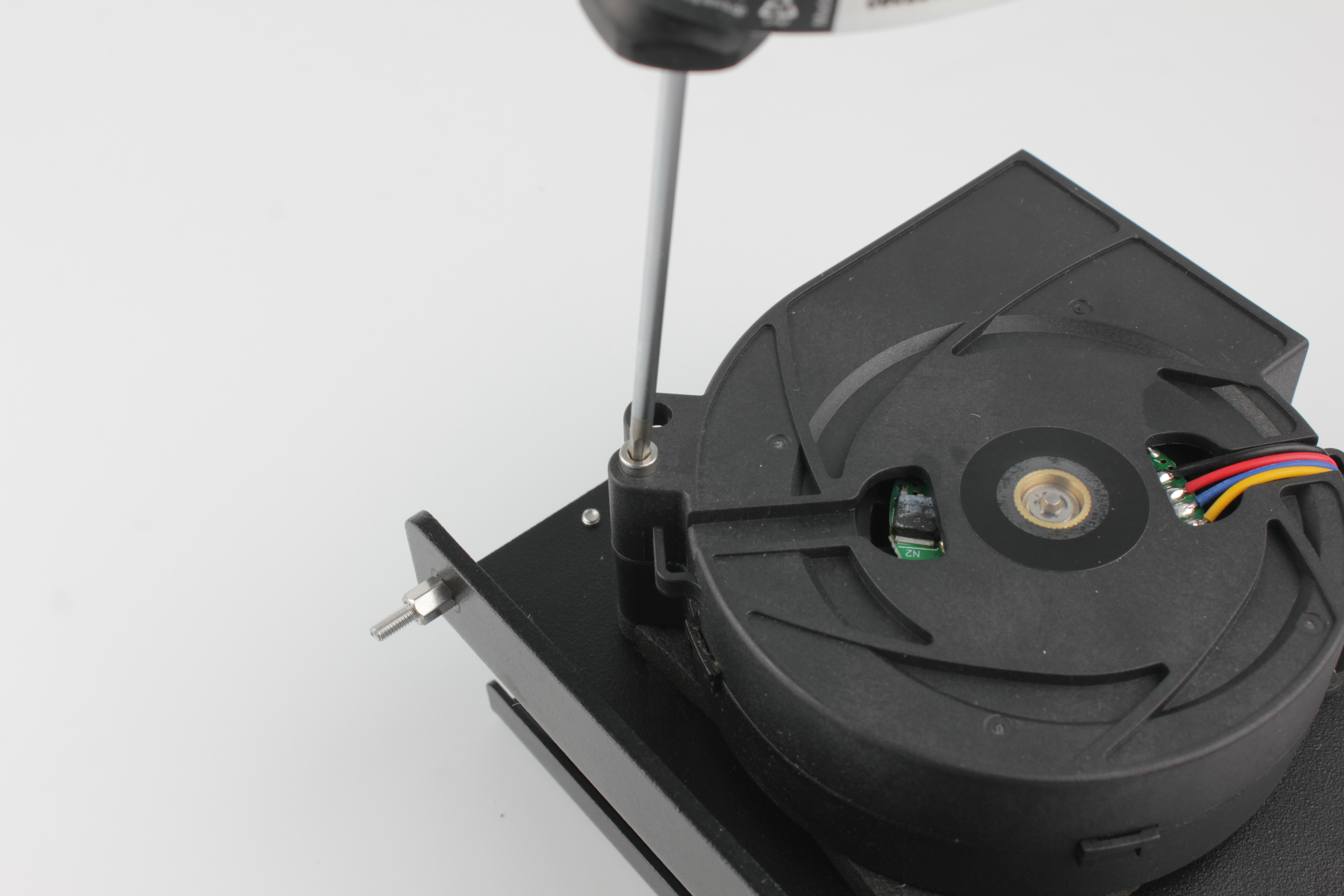
5. Removing the fan
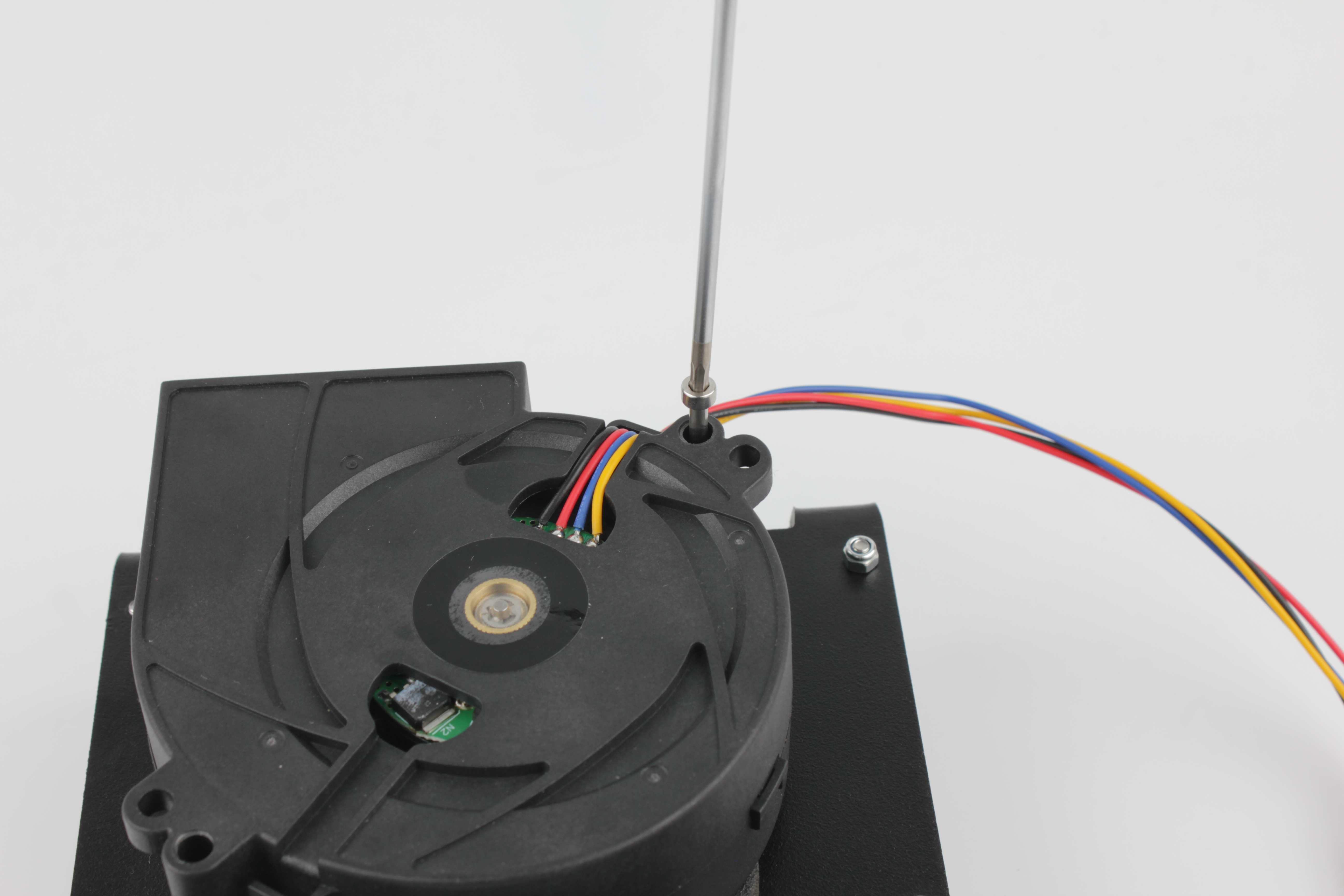
13. Unscrew the two fan mounting screws from the back of the bracket.
Use a 2.5 mm hex screwdriver.
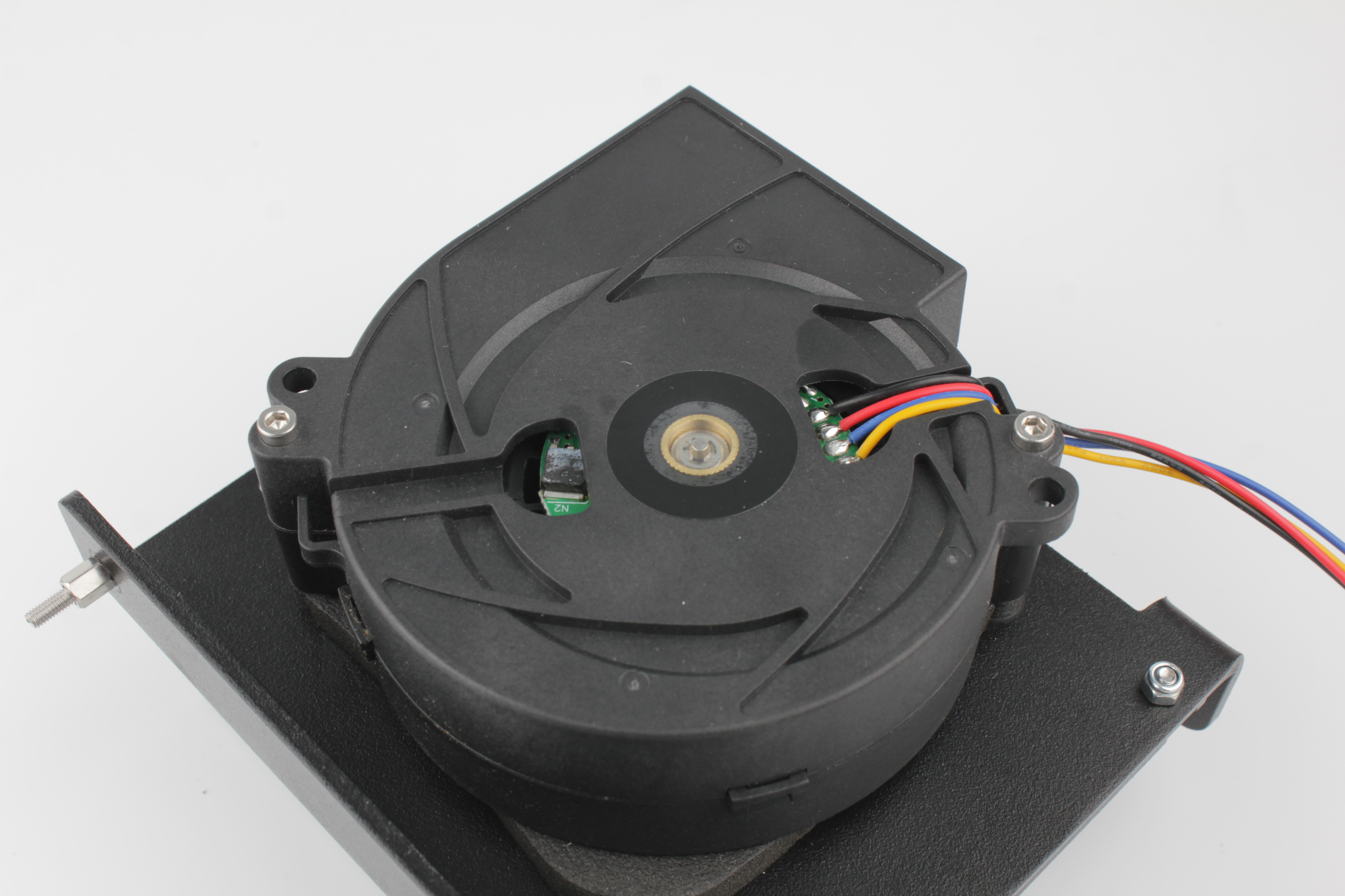
14. Remove the fan from the bracket.
Note the arrangement of the spacers and gasket:
- Each screw passes through a mounting ear on the bracket.
- A spacer sits on each screw.
- A gasket sits between the spacers, sandwiched between the fan and the bracket.
- The spacers limit how much the gasket is compressed, creating a sealed contact.
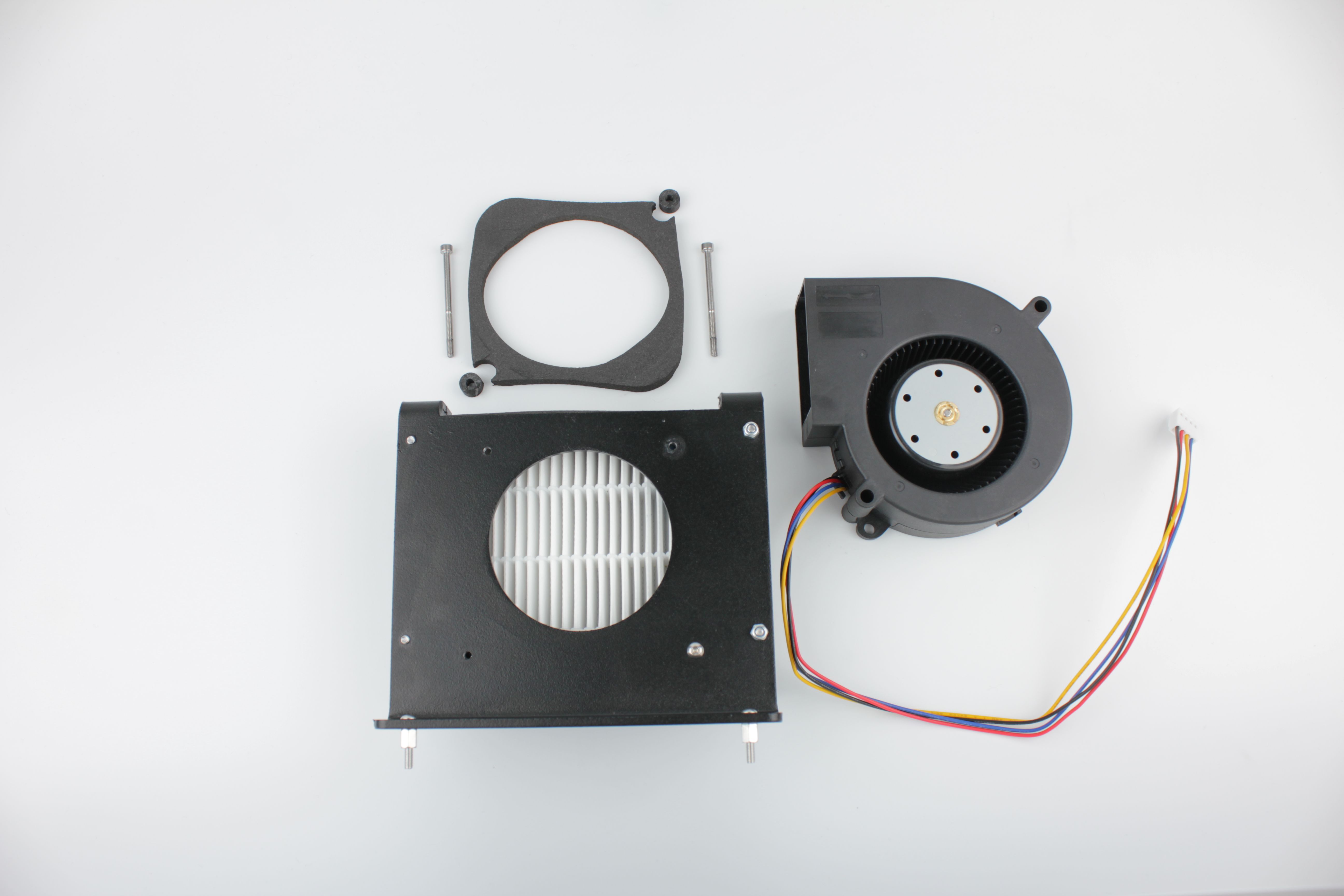
Reuse both spacers and the gasket
Keep both spacers and the gasket. They are reused with the new fan.
6. Installing the new fan
15. Position the gasket between the two spacers in the same arrangement as the original.
16. Place the new fan on the bracket with the spacers and gasket in place.
17. Apply threadlocker (Loctite 243) to both fan mounting screws.
18. Insert the screws through the bracket mounting ears and tighten with a 2.5 mm hex screwdriver.
Do not overtighten – the spacers set the correct compression on the gasket.
7. Reassembly
19. Route the fan cable through the wall hole to the electronics bay.
Position the bracket assembly back inside the enclosure and secure with the two M3 nuts from the outside bottom using a 5.5 mm wrench.
20. Reinstall the cable grommet.
From the electronics bay side, route the fan cable behind the expansion board. Slide the cable grommet back onto the cable and press it into the enclosure wall hole.
21. Reconnect the HEPA fan cable to the expansion board in the rear electronics bay.
22. Place the stainless steel housing back over the bracket.
Secure with the four screws using a 2.5 mm hex screwdriver. Apply threadlocker before tightening.
Replace older 2 mm housing screws when convenient
If you still have the older 2 mm button head screws, this is a good time to replace them with socket head cap screws of the same length that take a 2.5 mm hex.