XY Motor
This guide covers replacing the XY-axis motors on the Vision Miner 22IDEX V4. The machine has four motors in the XY motion system:
| Motor | Qty | Orientation | Location |
|---|---|---|---|
| Y-axis motors | 2 | Horizontal | Rear electronics compartment – one on the left side, one on the right side |
| Tool motors | 2 | Vertical | Rear electronics compartment – one on the left side (Tool 0), one on the right side (Tool 1) |
Common reasons for motor replacement: excessive vibration, grinding noise, skipped steps during printing, or visible shaft damage. If the motor is fine but the pulley on it is worn or damaged, you can replace just the pulley – see the XY Pulley Replacement Guide.
Before you begin - safety and risk
Read the Safety - Before You Begin article to understand the hazards involved in working on the Vision Miner 22IDEX V4 - including electrical, thermal, mechanical, and chemical risks. All procedures in this wiki are provided as recommendations only. By choosing to follow any procedure, you do so at your own risk.
Tools and Materials
- 2.5 mm Hex screwdriver (hex wrench) – for top cover screws, motor bracket screws, and motor mounting screws
- 2 mm Hex screwdriver (hex wrench) – for cover limiter screws and pulley set screw (if transferring pulley)
- Replacement motor
- Threadlocker (we recommend Loctite 243)
- Guitar tuning app on your phone (for verifying belt tension at 65 Hz after reassembly)
- Small container or magnetic tray (to hold screws and small parts)
Removing Belt Tensioners
- Fully unscrew the belt tensioning knobs on the front of the machine, turning counter-clockwise. Remove them completely.
- Catch the washer behind each knob – it will fall off as you remove the knob. Set the knobs, springs, and washers aside.
- Pull the belt tensioners out of their housings so they hang freely on the belts.
Disconnecting Motor Cables
- Disconnect the cables from the old motors (two motors on one bracket). Grip the connector body – not the wires – and pull straight out. Turn off the printer, unplug the mains cable, and wait at least 60 seconds for capacitors to discharge before touching motor wiring or terminals. Do not pull or bend motor wires – grip the connector body and pull straight out. Photograph connector orientation before disconnecting to ensure correct reconnection later.
Removing the Top Cover
- Unscrew the eight screws holding the top cover using the 2.5 mm hex screwdriver.
- Unscrew the two screws holding the cover limiter using the 2 mm hex screwdriver.
- Remove the top cover from the printer.
Removing the Motor Bracket
- Unscrew the two screws on the top gantry that hold the motor bracket using the 2.5 mm hex screwdriver.
- Unscrew the two screws on the side wall that hold the motor bracket using the 2.5 mm hex screwdriver.
- Pull the bracket toward you – it will stretch out with the belts still attached.
- Slip the belts off the motor pulleys and remove the bracket from the printer.
Removing Motors from the Bracket
- Unscrew the motor mounting screws using the 2.5 mm hex screwdriver.
- Remove the motor from the bracket. Note the motor orientation relative to the bracket.
- Repeat steps 12–13 for the second motor if it also needs to be replaced.
Transferring the Pulley (if reusing the old pulley)
- Loosen the set screw on the old motor's pulley using the 2 mm hex screwdriver.
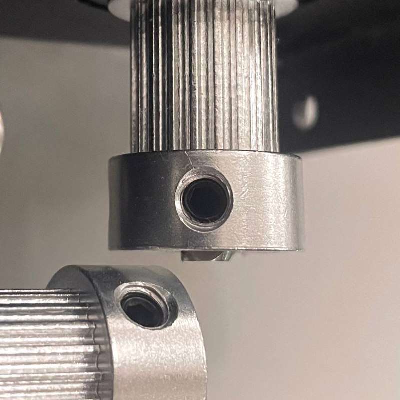
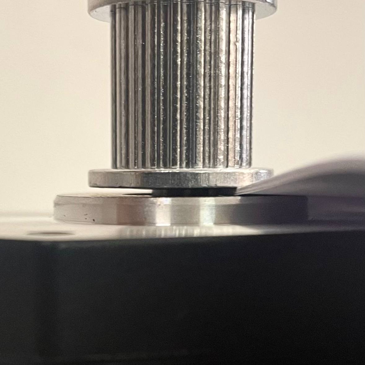
- Slide the pulley off the old motor shaft. Note how far down the shaft the pulley was seated – you will need to replicate this position on the new motor. You can replicate this measurement using A4 paper: fold it 4 times and use it as a distance spacer.
- Slide the pulley onto the new motor shaft at the same position. The flat side of the shaft (D-cut) must align with the set screw.
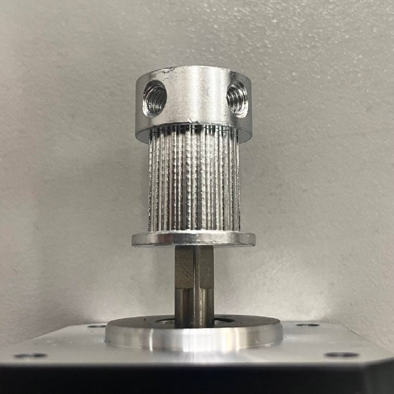
- Tighten the set screw firmly. The pulley should not wobble or slide on the shaft.
Installing New Motors on the Bracket
- Position the new motor on the bracket in the same orientation as the old one.
- Apply threadlocker to the mounting screws.
- Insert the screws and tighten evenly using the 2.5 mm hex screwdriver.
- Repeat steps 19–21 for the second motor if also replacing it.
Reassembly
- Loop the belts back onto the motor pulleys. Make sure the teeth face inward toward the pulleys.
- Install the bracket with motors back into the printer. Apply threadlocker to the screws. Insert the two screws on the side wall and tighten with the 2.5 mm hex screwdriver.
- Insert the two screws on the top gantry with the 2.5 mm hex screwdriver. Apply threadlocker to the screws. After all 4 screws are started, tighten them.
- Place the top cover back on the printer. Insert the eight top cover screws and tighten with the 2.5 mm hex screwdriver. Use threadlocker. Pay attention to the cables that pass through the cover spacer – they should pass through freely.
- Insert the two cover limiter screws and tighten with the 2 mm hex screwdriver.
- Reconnect the motor cables to the connectors on the motors. Match the connector orientation to the photos taken in step 4.
Reinstalling Tensioners and Belt Tension
- Insert the belt tensioners back into their housings.
- Place the washers onto the tensioning knob shafts. Screw the knobs back in clockwise.
- Set belt tension to 65 Hz using a guitar tuning app. For the full tensioning procedure, see the Belt Tensioning Guide.
-
Repeat the full procedure for the other side if motors on both sides need replacement. The process is identical.
-
Slide the gantry and toolheads manually across their full range of travel. Movement should be smooth with no binding or unusual noise.
FAQ
Troubleshooting
Support
If you could not find an answer here, reach out to our support team.