Z-Rail Retrofit Kit
This guide covers installing the Z-Rail Mounting Retrofit Kit on early Vision Miner 22 IDEX V4 machines. The kit replaces the original standard nuts with standoffs and spherical washers, providing a more vibration-resistant and self-aligning Z-rail mounting.
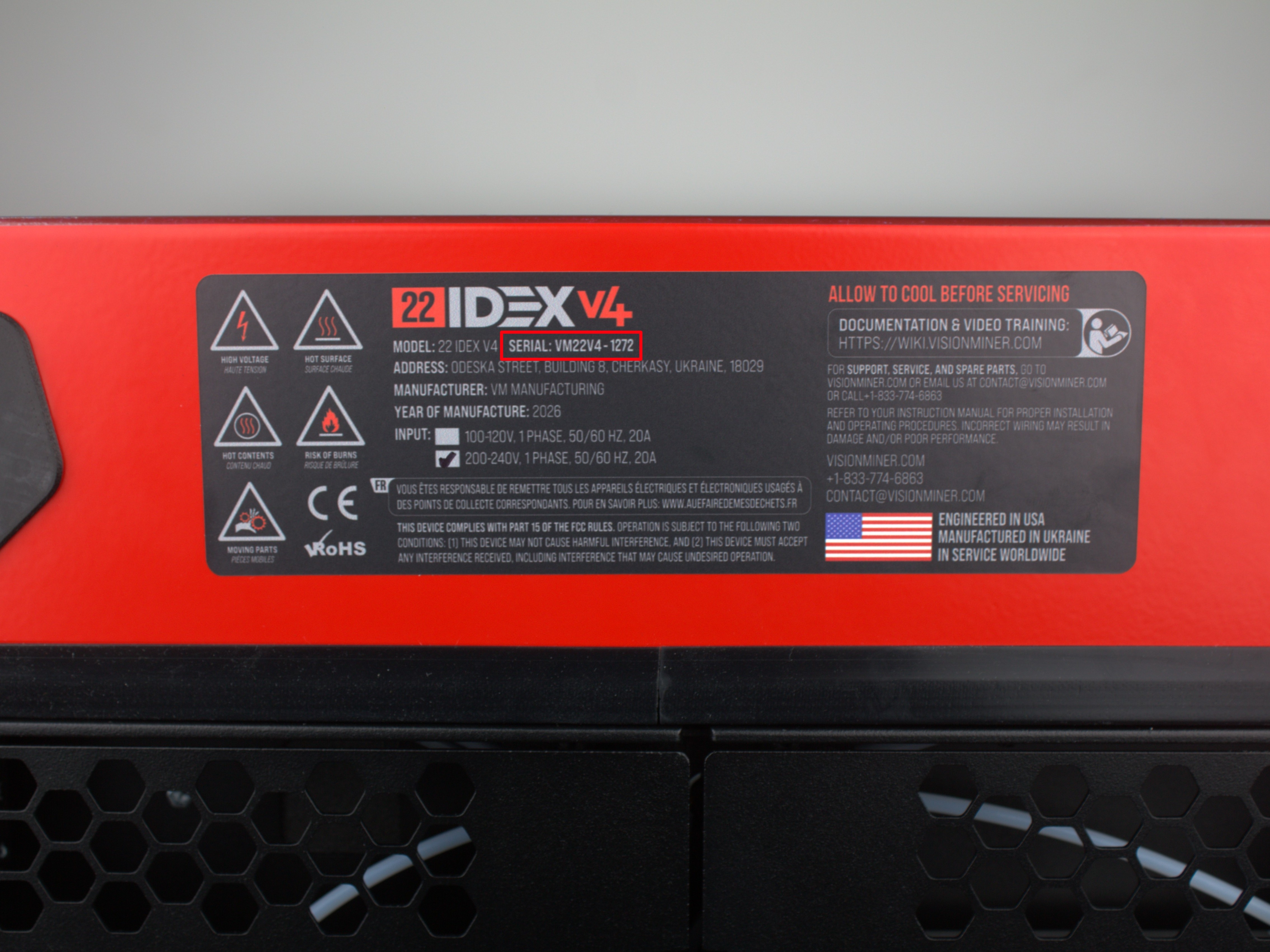
The updated mounting design uses standoffs and spherical washers that self-align, provide more thread engagement, and are more vibration-resistant. This kit is available as a free upgrade for all V4 customers with serial number below 295. Contact Vision Miner Support to request yours.
Your serial number is located on the back of the red lid.
The procedure is straightforward - you replace one mounting point at a time without removing the rails, bed, or any other components.
Before you begin - safety and risk
Read the Safety - Before You Begin article to understand the hazards involved in working on the Vision Miner 22IDEX V4 - including electrical, thermal, mechanical, and chemical risks. All procedures in this wiki are provided as recommendations only. By choosing to follow any procedure, you do so at your own risk.
Power off and discharge
Turn off the printer and unplug it from the power outlet. Wait at least 60 seconds for capacitors to discharge. Wait for the nozzles, bed, and chamber to cool to room temperature before starting any work. The printer must be completely off and cold to the touch.
Tools and Materials
- 2.5 mm Hex screwdriver (hex wrench) - for Z-rail screws and wiring panel cover screws
- 5.5 mm Wrench - for removing the original Z-rail nuts
- 5 mm Wrench - for the new standoffs
- Tweezers (optional) - in case a spherical washer falls during installation
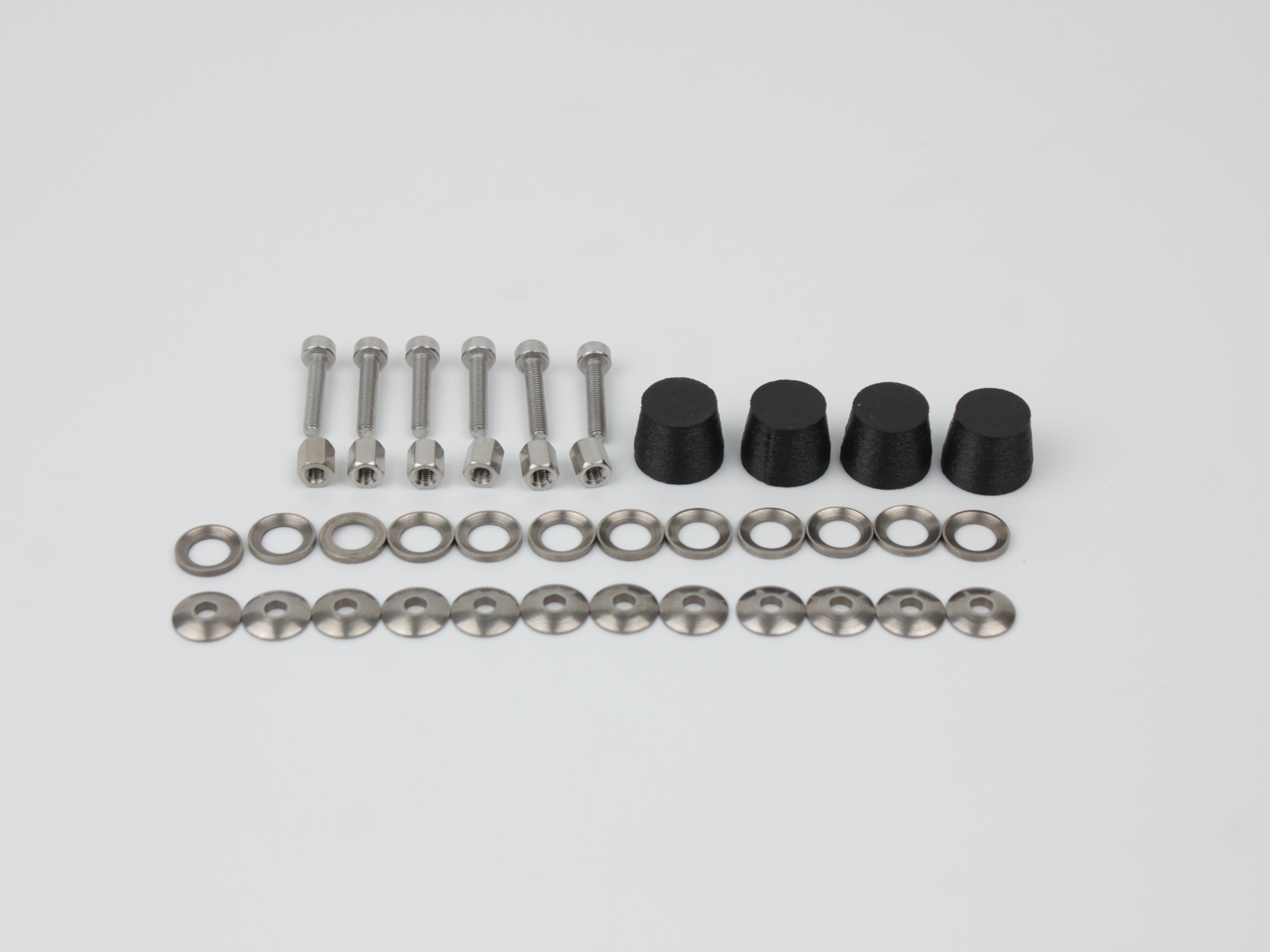
Kit Contents
| Part | Qty | Description |
|---|---|---|
| M3x16 screw | 6 | Replaces original screws (2 per rail - 3 rails) |
| Spherical washer pair (concave + convex) | 12 pairs | Self-aligning washers (2 pairs per screw - one inside, one outside) |
| M3x6 standoff | 6 | Replaces original nuts (1 per screw) |
| Cap | 4 | Covers the standoffs on the front rails only |
How the Mounting Works
Each Z-rail mounting point is a sandwich of layers. From outside to inside:
- Standoff (replaces the old nut)
- Spherical washer pair - outer (concave + convex)
- Printer frame
- Spherical washer pair - inner (concave + convex)
- Z-rail
All versions of the printer already have the inner spherical washer pair between the frame and the rail. If your machine does not have the outer pair, the kit includes them.
1. Replacing the Front Z-Rail Hardware
The front has four mounting points - two per rail (top and bottom), on the left and right sides. Replace them one at a time.
Work one mounting point at a time
Do not remove more than one screw at once.
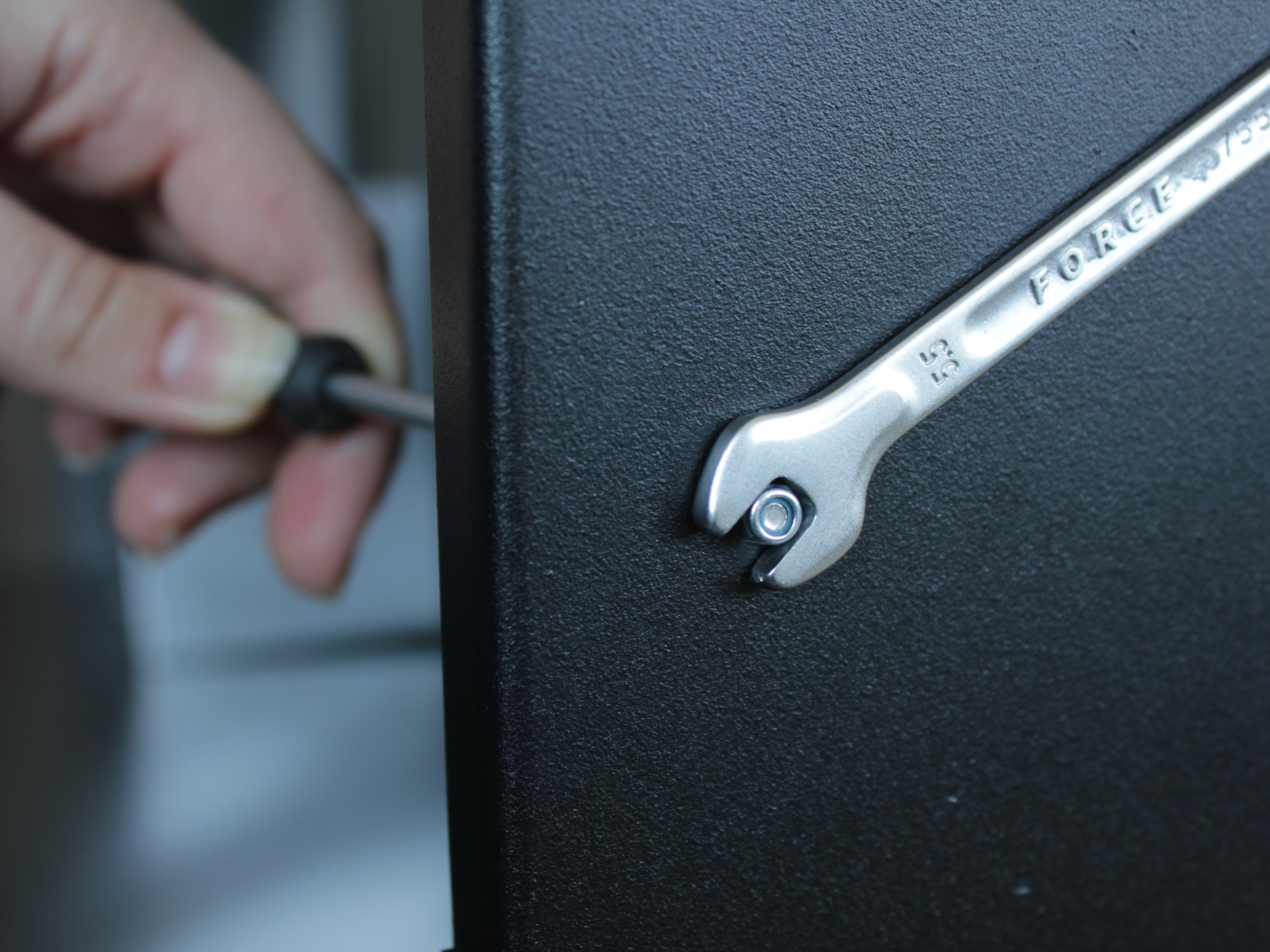
- Using the 5.5 mm wrench, unscrew the old nut from one mounting point. Leave the old bolt in place - do not pull it out yet.
-
If your machine does not have the outer spherical washer pair at this position, place one pair from the kit onto the new M3x16 screw.
-
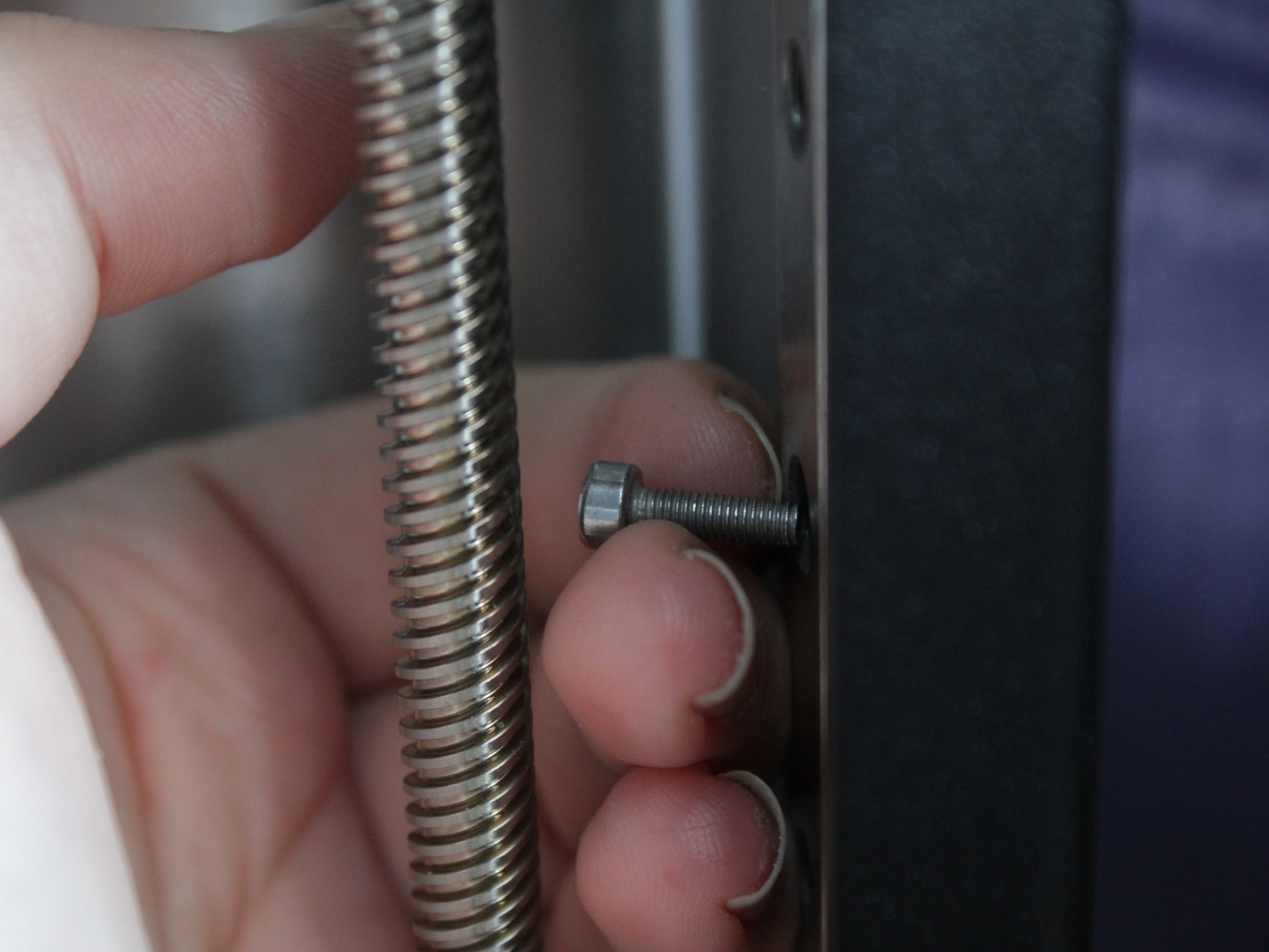
From the outside, push the new bolt into the hole. The new bolt pushes the old bolt out from behind while passing through the inner spherical washers - this keeps the inner washers in place and prevents them from falling.
If a washer falls
If a spherical washer falls during the swap, retrieve it by hand or with tweezers and place it back.
-
Once the new bolt is through, add the outer spherical washer pair (if not already on the bolt) and thread the new standoff onto the screw.
-
Hold the standoff with the 5 mm wrench and tighten the screw with the 2.5 mm hex screwdriver.
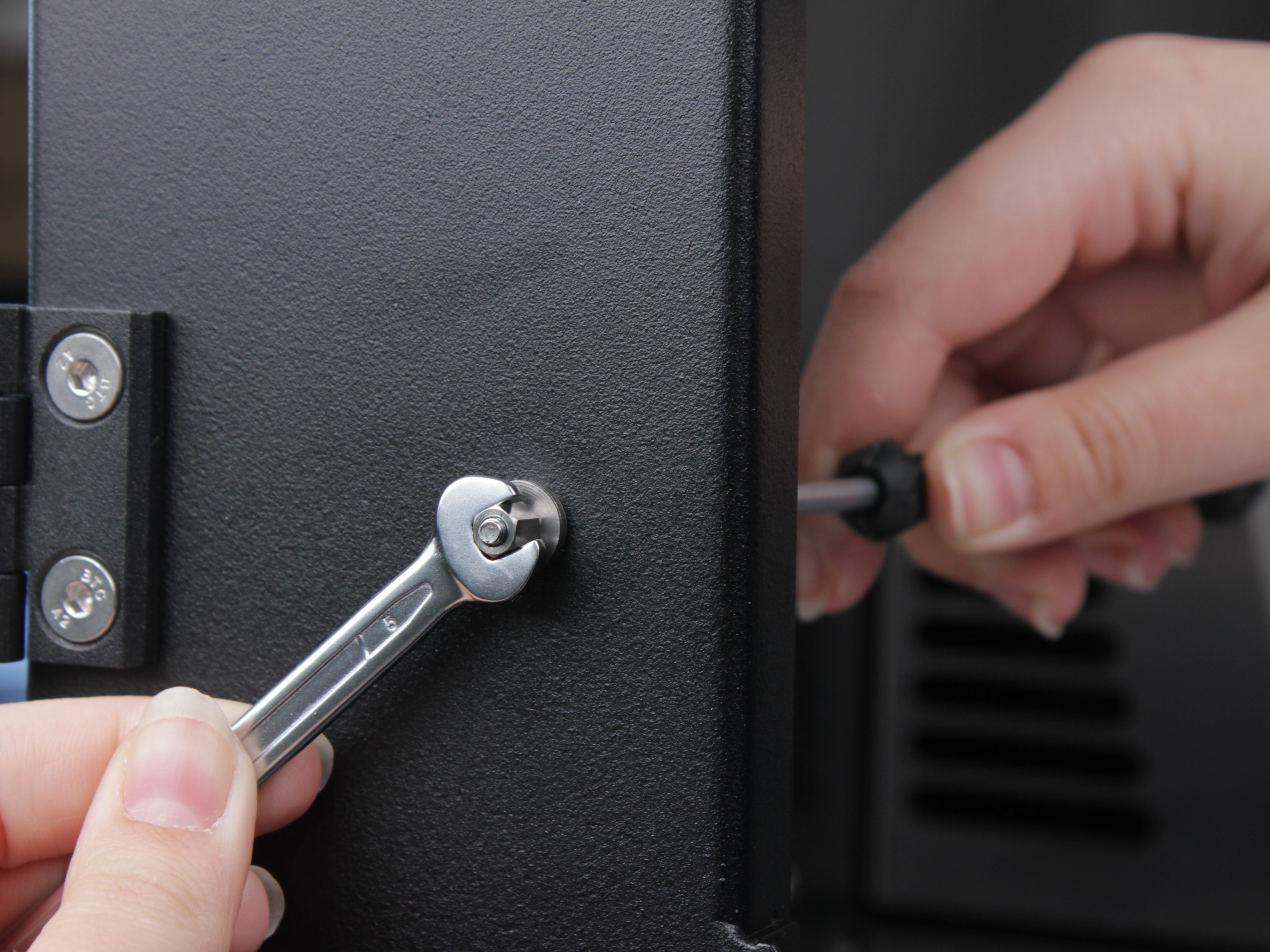
Torque specification
The recommended torque is 1.5 Nm. If you have the torque wrench from the nozzle kit with a 2.5 mm hex adapter, you can use it. Otherwise, hand-tight is fine - the new standoffs are much harder to strip than the old nuts.
-
Repeat steps 1-5 for the remaining three front mounting points (right top, right bottom, left top, left bottom).
-
Install a cap onto each of the four front standoffs.
- Check both front supports with the wiggle test - grab each support firmly and try to wiggle it side-to-side. There should be zero play.
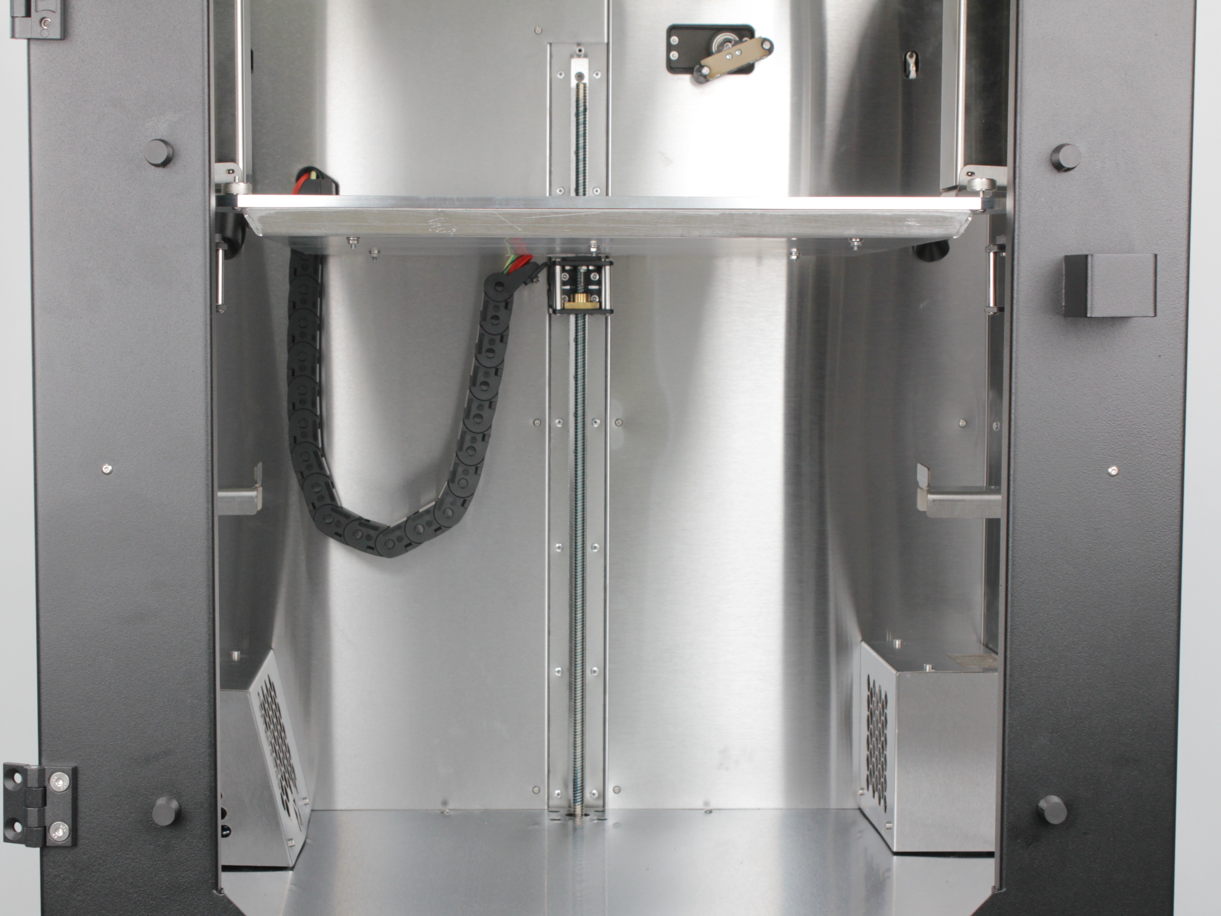
2. Replacing the Back Z-Rail Hardware
The back rail has two mounting points. The procedure is exactly the same as the front, but you need to remove the wiring panel cover to access them.
- Locate the vertical cable channel cover on the back of the printer.

It is secured with six M3 screws, two upper:

Two middle:

Two lower:

- Using the 2.5 mm hex screwdriver, remove all six screws and carefully remove the cover.
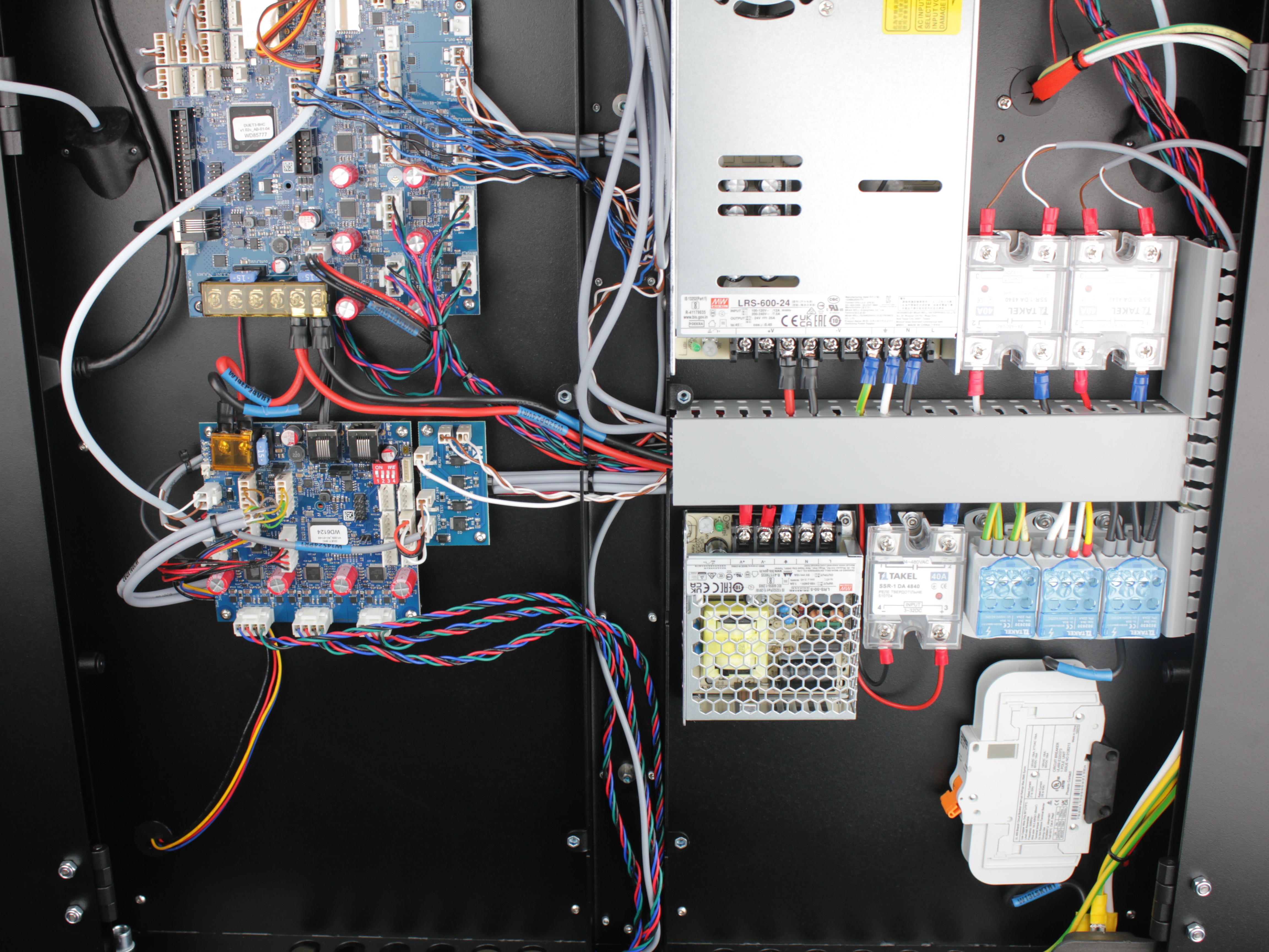
Do not strain wires
Be careful not to pull or strain any wires when removing the panel cover.
- Replace each of the two back mounting points using the same procedure from steps 1-5: unscrew old nut, push old bolt out with new bolt, add outer washers if needed, thread on standoff, tighten. The back rail does not use caps - only the front rails get caps.
Upper mounting screw for back Z-rail:
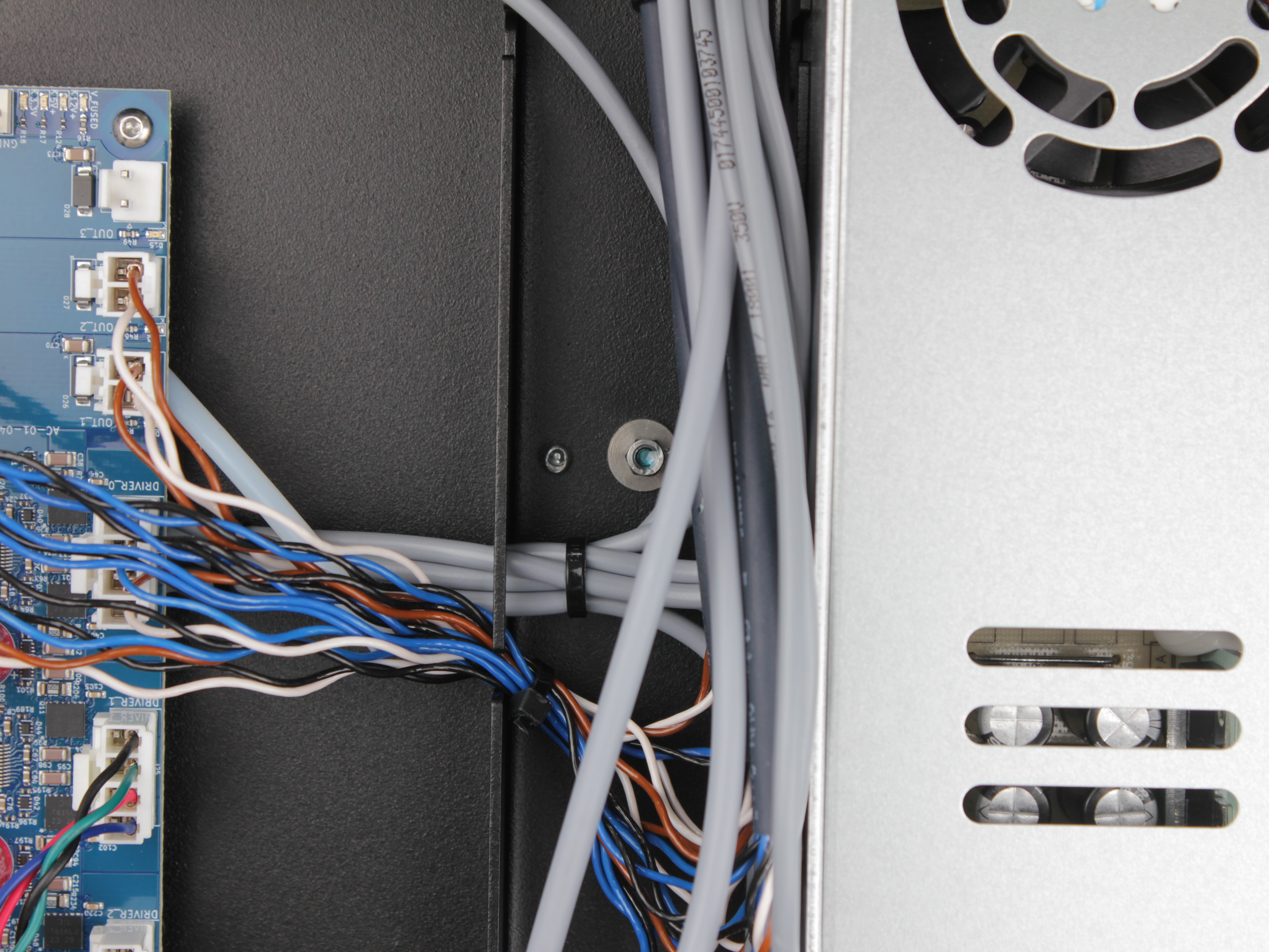
Lower mounting screw for back Z-rail:
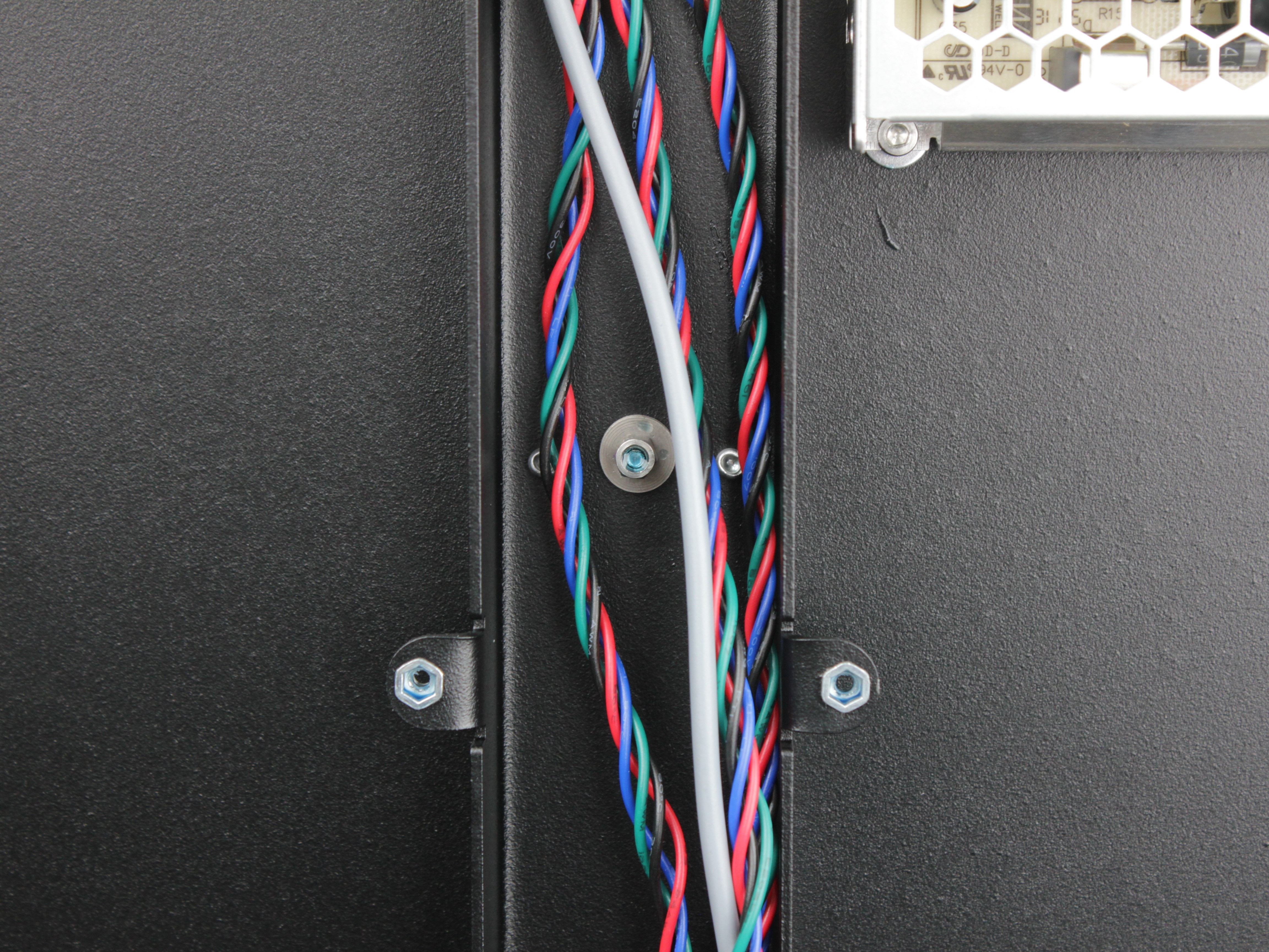
Wires in this area
Work carefully - there are wires in this area. Do not damage or pinch any wiring while working.
-
Check the back support with the wiggle test - there should be zero play.
-
Reinstall the wiring panel cover and secure it with the M3x6 screws.
3. Verification
- Run a test print to verify the Z-wobble is resolved.
For Z-wobble troubleshooting, see Troubleshooting Z-Wobble.
Troubleshooting
FAQ
Support
If you could not find an answer here, reach out to our support team.