Z-Wobble
This guide covers how to diagnose and fix Z-wobble (also called Z-banding) on the Vision Miner 22IDEX V4. Z-wobble causes a repetitive banding pattern on printed parts at regular intervals. The most common causes are:
- Filament diameter inconsistency – even small variations in filament diameter exponentially affect volumetric flow rate, producing visible banding at regular intervals. Try a different spool from a different batch to rule this out.
- Build plate PID overshoot – especially common when printing with low-temperature materials (bed below 120–130 °C). The build plate heater is factory-calibrated for high-temperature printing. At lower temperatures, the PID controller overshoots and oscillates, causing the bed to expand and contract cyclically. This creates visible horizontal lines along the Z-axis. See section 2.
- Thermal expansion and extrusion settings – differences in print time between infill and solid top surfaces cause uneven cooling and contraction, which can produce visible lines. Over-extrusion can also contribute to surface inconsistencies along the Z-axis.
- Mechanical play – the least common cause. Loose components in the Z-rail mounting or extruder can introduce physical play that shifts layers during printing.
Filament and PID overshoot are the two most common causes. Start by trying a different spool, then run PID tuning (fully automatic). If the issue persists, proceed to the mechanical and extruder checks.
Before you begin - safety and risk
Read the Safety - Before You Begin article to understand the hazards involved in working on the Vision Miner 22IDEX V4 – including electrical, thermal, mechanical, and chemical risks. All procedures in this wiki are provided as recommendations only. By choosing to follow any procedure, you do so at your own risk.
Do not over-tighten Z-rail screws
On machines with the older mounting configuration (standard nuts), the threads can strip easily. Tighten with firm but controlled force – stop as soon as the connection is snug.
Tools and Materials
- 2.5 mm Hex screwdriver (hex wrench) – for Z-rail screws and wiring panel cover screws
- 5 mm Wrench – for Z-rail standoffs (newer machines, serial number 295 and above)
- 5.5 mm Wrench – for Z-rail nuts (older machines, serial number below 295)
1. Filament Check
Filament diameter inconsistency is one of the most common causes of Z-wobble artifacts. Even small variations in diameter exponentially affect volumetric flow rate, creating visible banding at regular intervals.
- Try a different spool from a different batch or manufacturer.
- To confirm whether filament is the cause, print two identical parts in mirror mode next to each other – one spool on each toolhead, using different manufacturers or batches. If only one part shows the artifacts, the filament on that side is likely the cause.
- If the issue persists with multiple spools, proceed to PID tuning below.
2. Build Plate PID Tuning
This is a common fix and fully automatic.
The build plate heater PID is factory-calibrated for high-temperature printing (typically above 130 °C). When you print materials that need a lower bed temperature – such as PLA, PETG, or ABS – the PID controller can overshoot the setpoint, then compensate too far in the other direction, and repeat. Each overshoot causes the build plate to thermally expand, and each dip causes it to contract. These expansion/contraction cycles produce visible horizontal lines at regular intervals along the Z-axis.
Recalibrating the PID at the temperature you actually use fixes this.
- In the Web Interface, navigate to Macros → System → Calibration → Temperature Tuning → PID Tuning Bed Heater.
- The macro will ask you to choose between the default temperature (150 °C) or a custom temperature. Select Custom temperature and enter the bed temperature you use most often (for example, 60 °C for PLA).
Do not interrupt PID auto-tune process
The PID auto-tune process takes several minutes. Do not leave the printer unattended. Do not interrupt the process – let it run to completion.
- Once the auto-tune completes, the new PID values are saved automatically.
- Run a test print to verify the Z-wobble lines are gone.
For more details, see Build Plate PID Tuning.
If Z-wobble persists after PID tuning, proceed to the mechanical checks below.
3. Mechanical Diagnostic Checks
Before starting, make sure the printer is powered off and everything is cold to the touch – build plate, nozzles, and chamber.
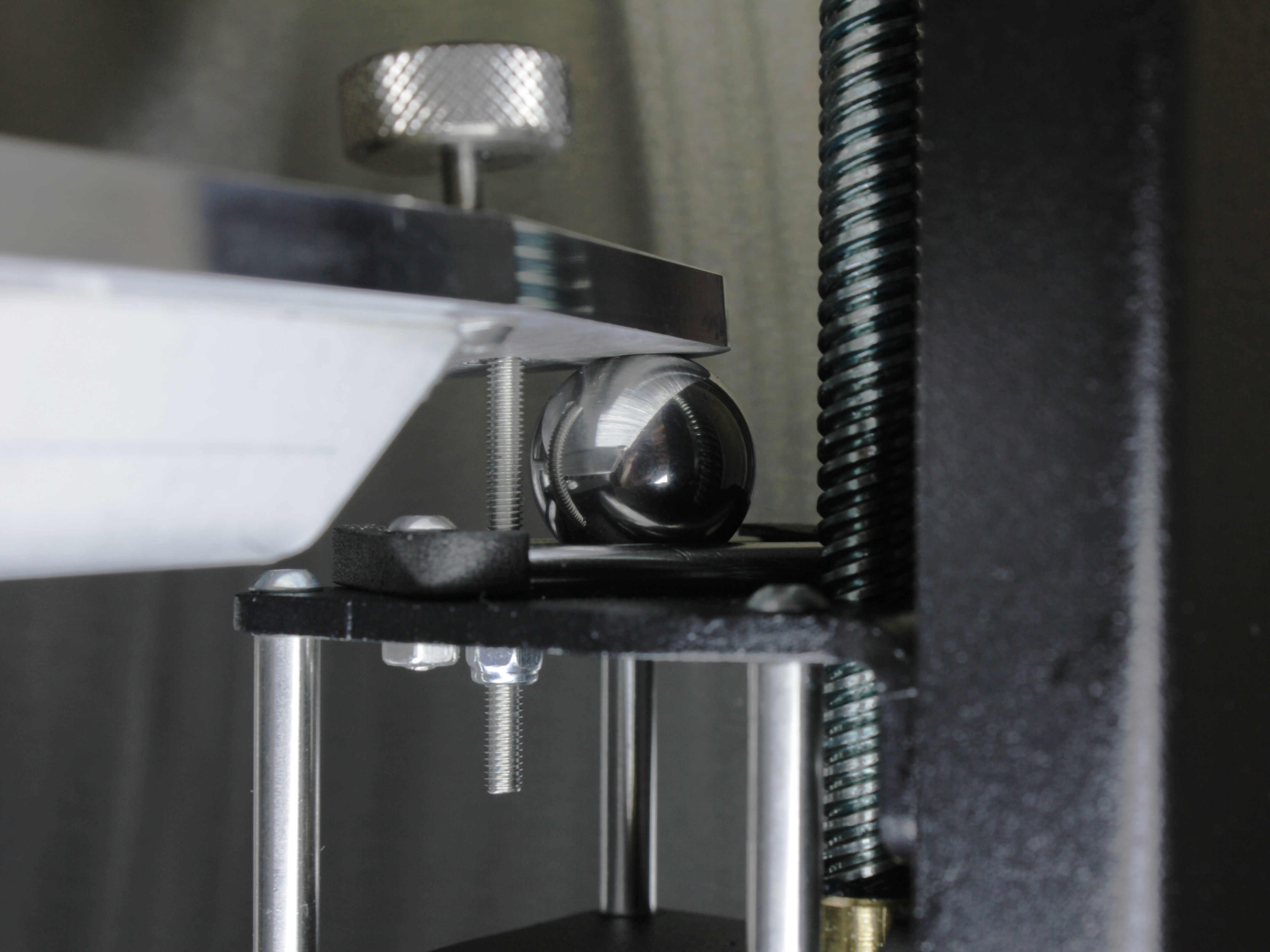
Build plate movement is normal
The build plate is kinematically coupled to the three build plate supports. It is expected for the build plate to have 2–4 mm of movement up and down – do not tighten those screws. They are securing screws only, and the build plate sits under its own weight. See Build Plate Securing Screws for details.
Check 1: Wiggle the build plate supports
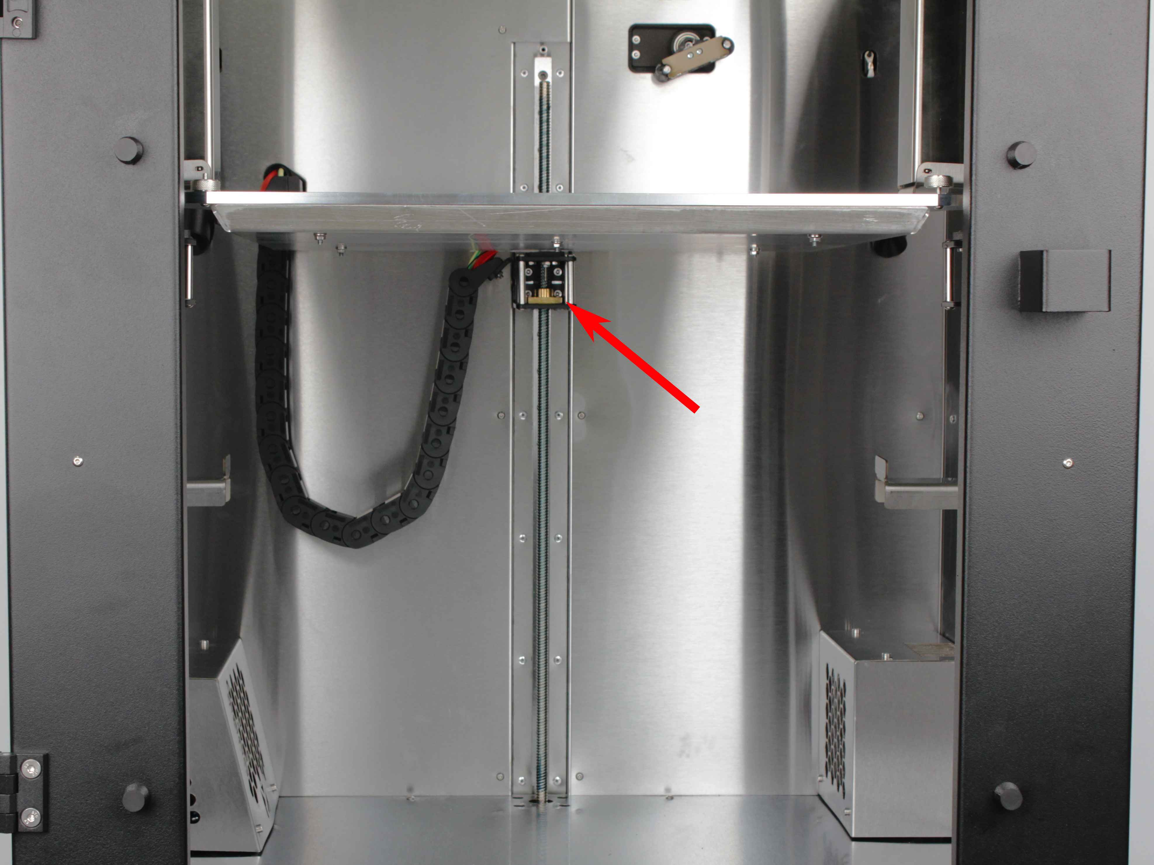
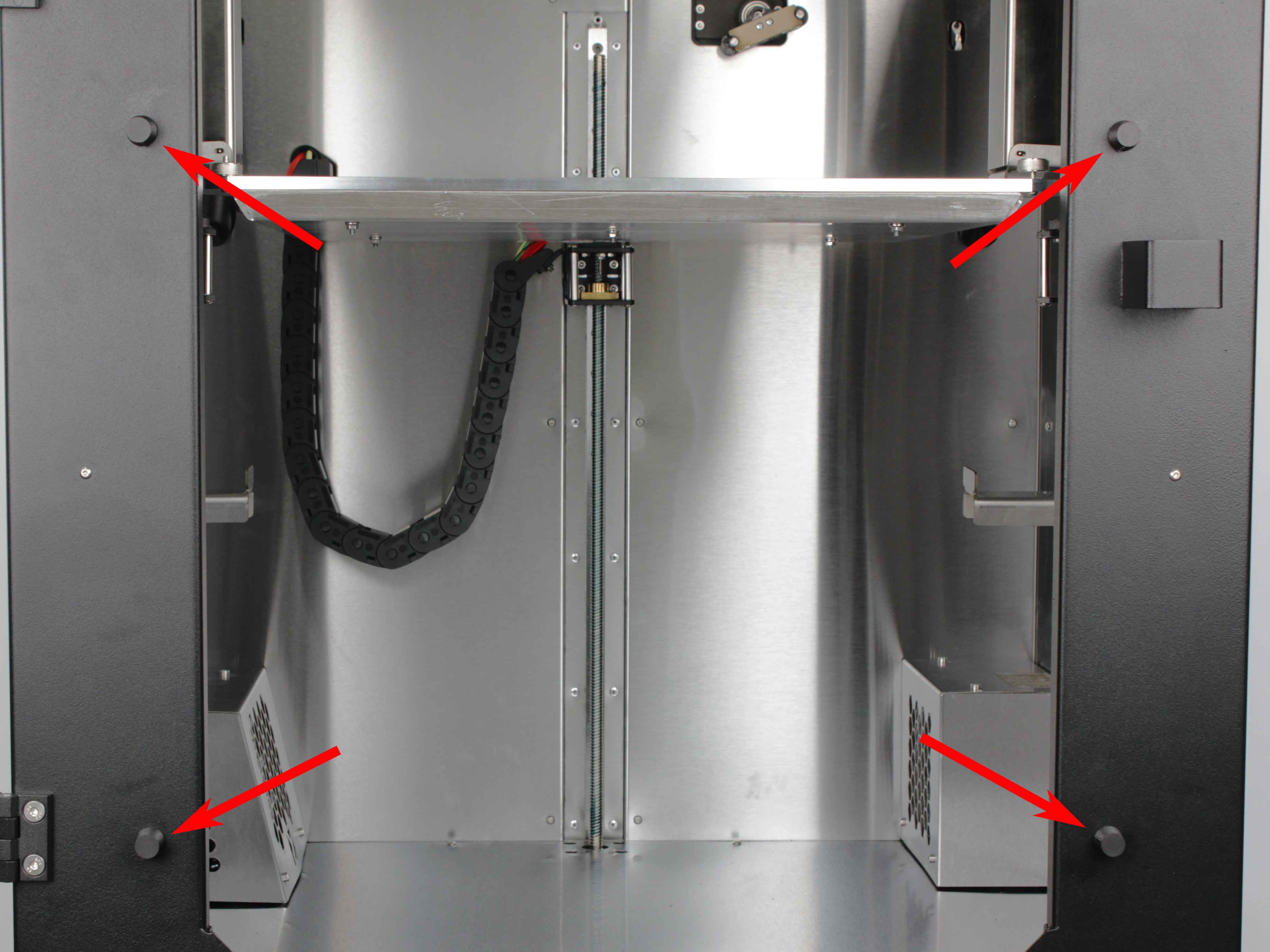
The Vision Miner 22IDEX V4 has three build plate supports – two in the front and one in the back. Each support rides on a Z-rail secured to the printer frame with two screws. If any of these screws loosen, the rail develops play and the build plate shifts during printing.
- Open the front door and locate the two front build plate supports.
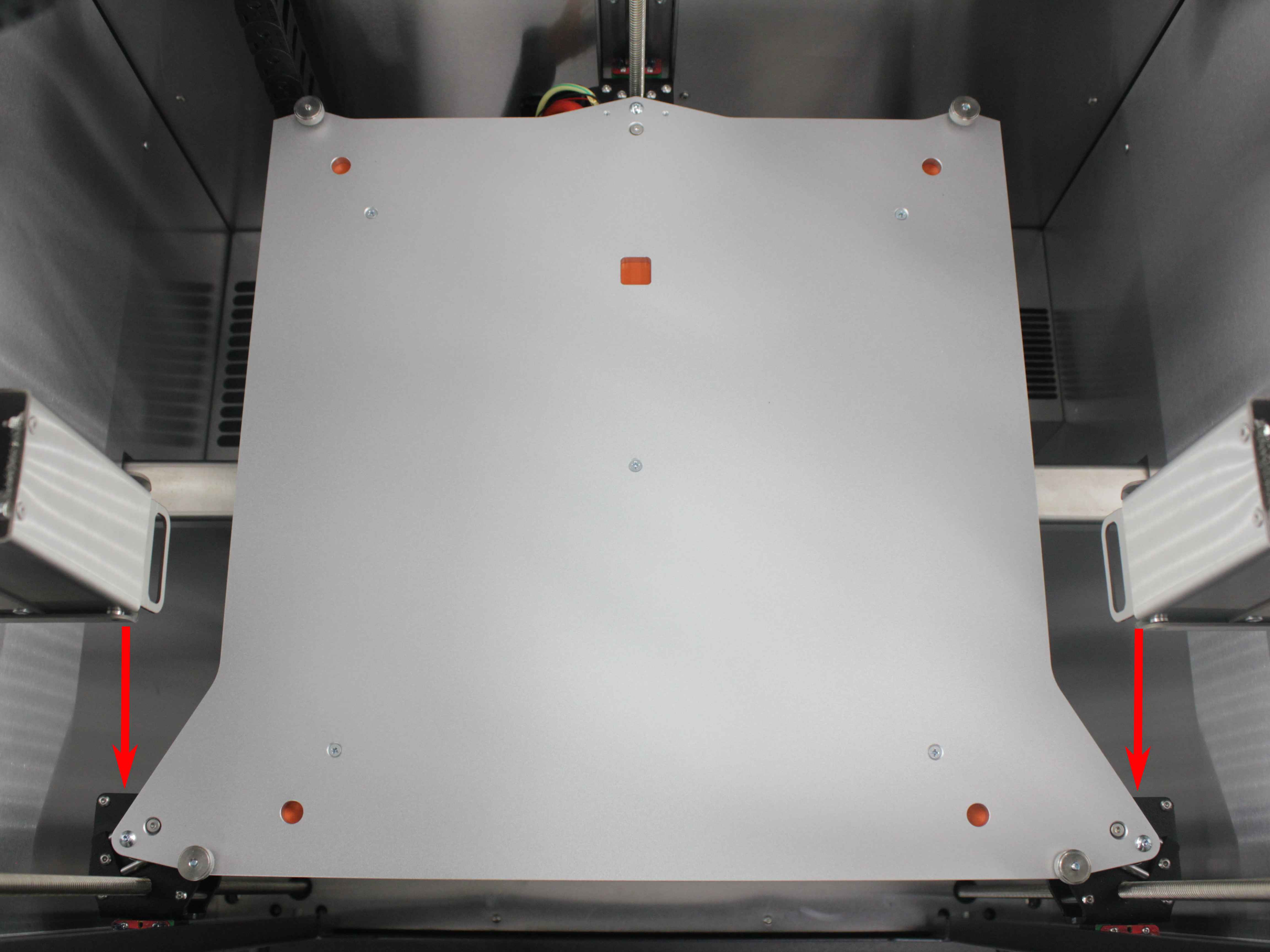
- Grab each front support firmly and try to wiggle it side-to-side (left-to-right). There should be zero play – the support should feel completely rigid. Any movement means the Z-rail screws have loosened.
- Locate the back build plate support (centered at the rear of the machine) and repeat the wiggle check.
If any support has play – proceed to tighten the Z-rail screws (sections 4 and 5).
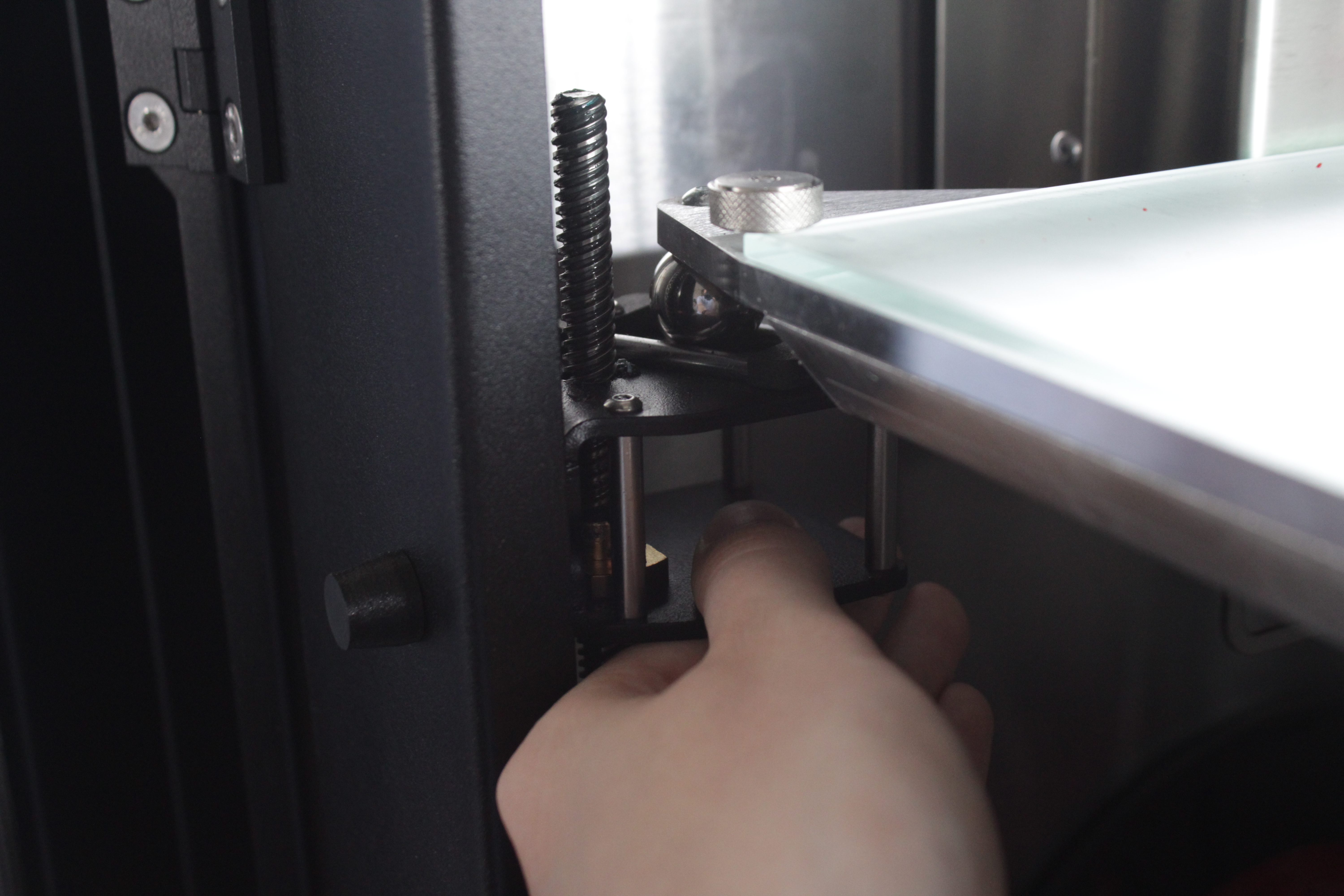
Check 2: Verify the build plate is seated properly
- Press down firmly on the center of the build plate. It should sit solidly on all three kinematic coupling points with no rocking. If the bed rocks or lifts off a support, it is not seated properly – lift the bed and reseat it.
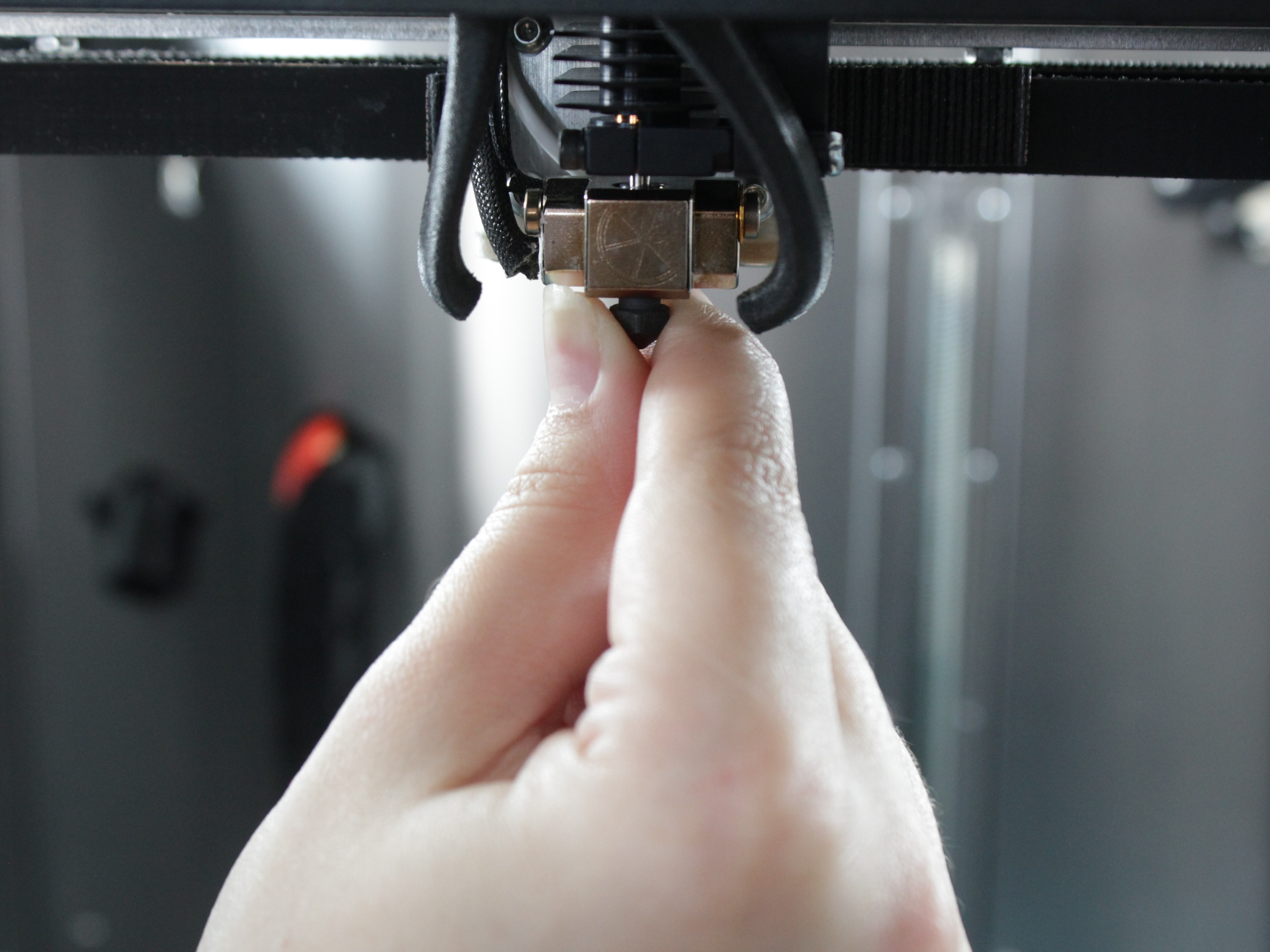
Check 3: Check the nozzle for play
- Grab the nozzle (or the heater block) firmly and try to wiggle it front-to-back, left-to-right, and up-and-down. There should be zero play in any direction. If you feel movement, the toolhead or hotend has a loose component – that needs to be addressed separately before continuing.
Check 4: Check the extruder
A defective extruder – for example, drive gears that are not perfectly round or have a manufacturing defect – can cause repetitive Z-wobble artifacts.
- Print two identical parts in mirror mode, placed close to each other.
- Inspect both parts. If only one part shows Z-wobble artifacts, the extruder on that toolhead is likely the cause – contact our support team. If both parts show the same artifacts, the cause is not extruder-specific – continue with the checks below.
What to do next
If any build plate supports have play, check whether your machine has the older or newer Z-rail mounting configuration:
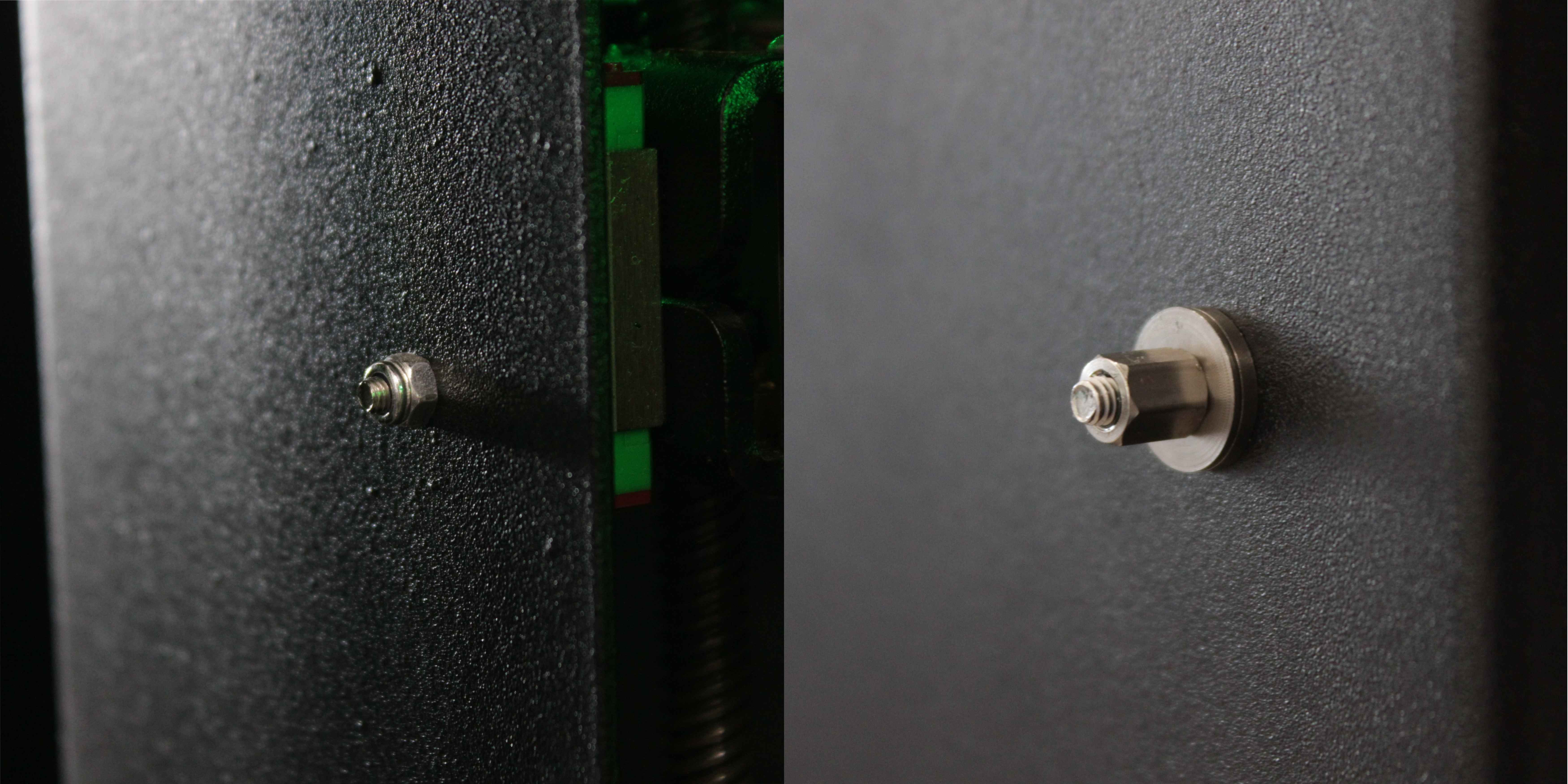
You can also check by serial number (located on the back of the red lid):
- Serial number below 295 – older configuration (standard nuts). Consider requesting the free Z-Rail Retrofit Kit.
- Serial number 295 and above – newer configuration (standoffs and spherical washers). Follow sections 4 and 5 below to tighten.
If all checks passed (no play anywhere) and both filament and PID tuning didn't help – contact our support team.
4. Tightening Front Z-Rail Screws
The front two Z-rails are easily accessible – the nuts or standoffs are visible from the front of the machine.
- Locate the two screws securing each front Z-rail. Each rail has one screw at the top and one at the bottom.
- Hold the nut or standoff with the wrench (5.5 mm or 5 mm – use whichever fits your machine) and tighten the screw with the 2.5 mm hex screwdriver. Tighten until snug – do not over-tighten.
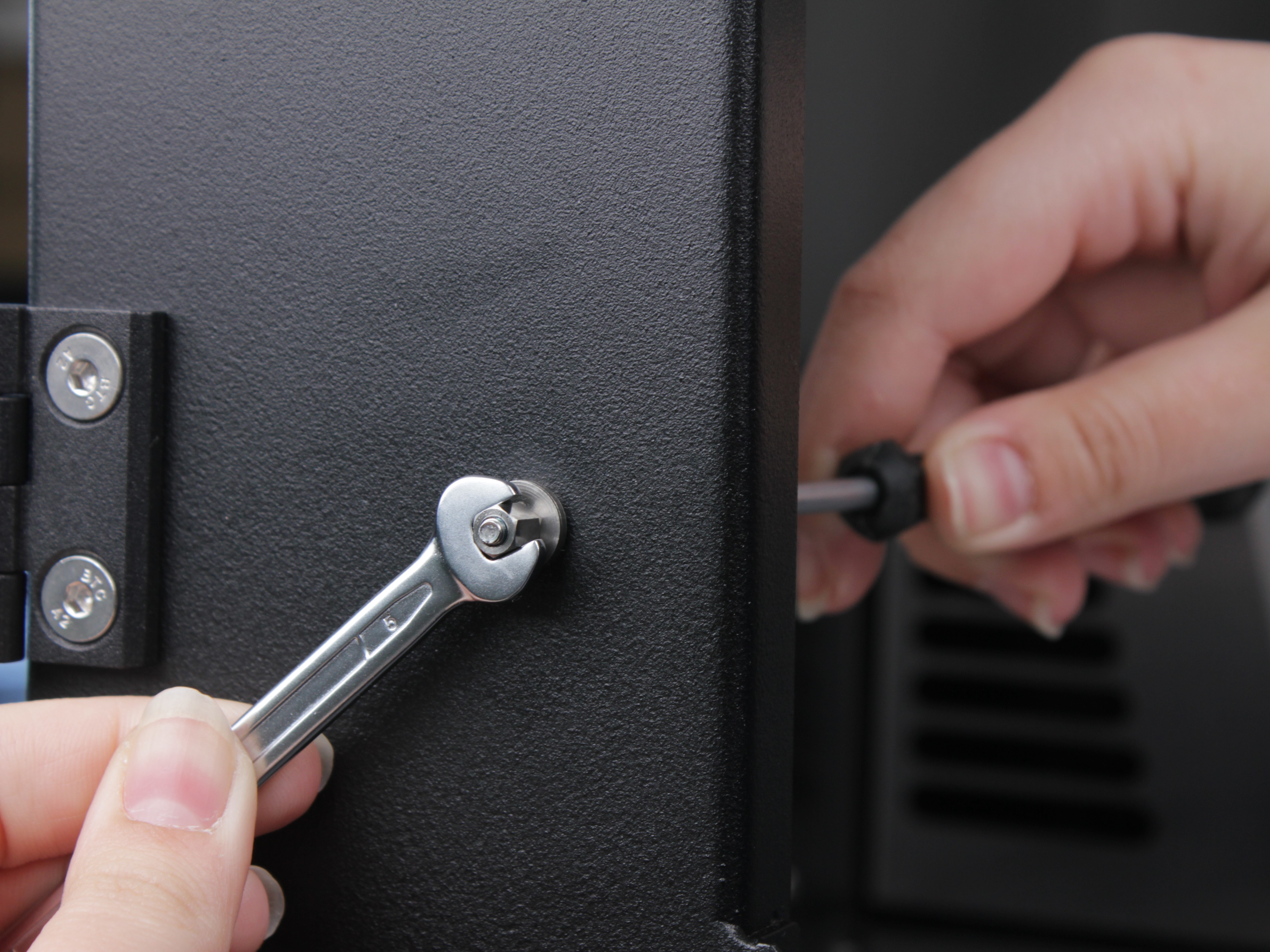
- Repeat for all four front screws (two per rail × two rails).
- After tightening, re-check each front support with the wiggle test (step 9). There should be no play.
5. Accessing and Tightening Back Z-Rail Screws
The back Z-rail nuts or standoffs are hidden behind the wiring panel cover at the rear of the machine.
- Locate the wiring panel cover on the back of the printer. It is secured with M3×6 socket head cap screws.
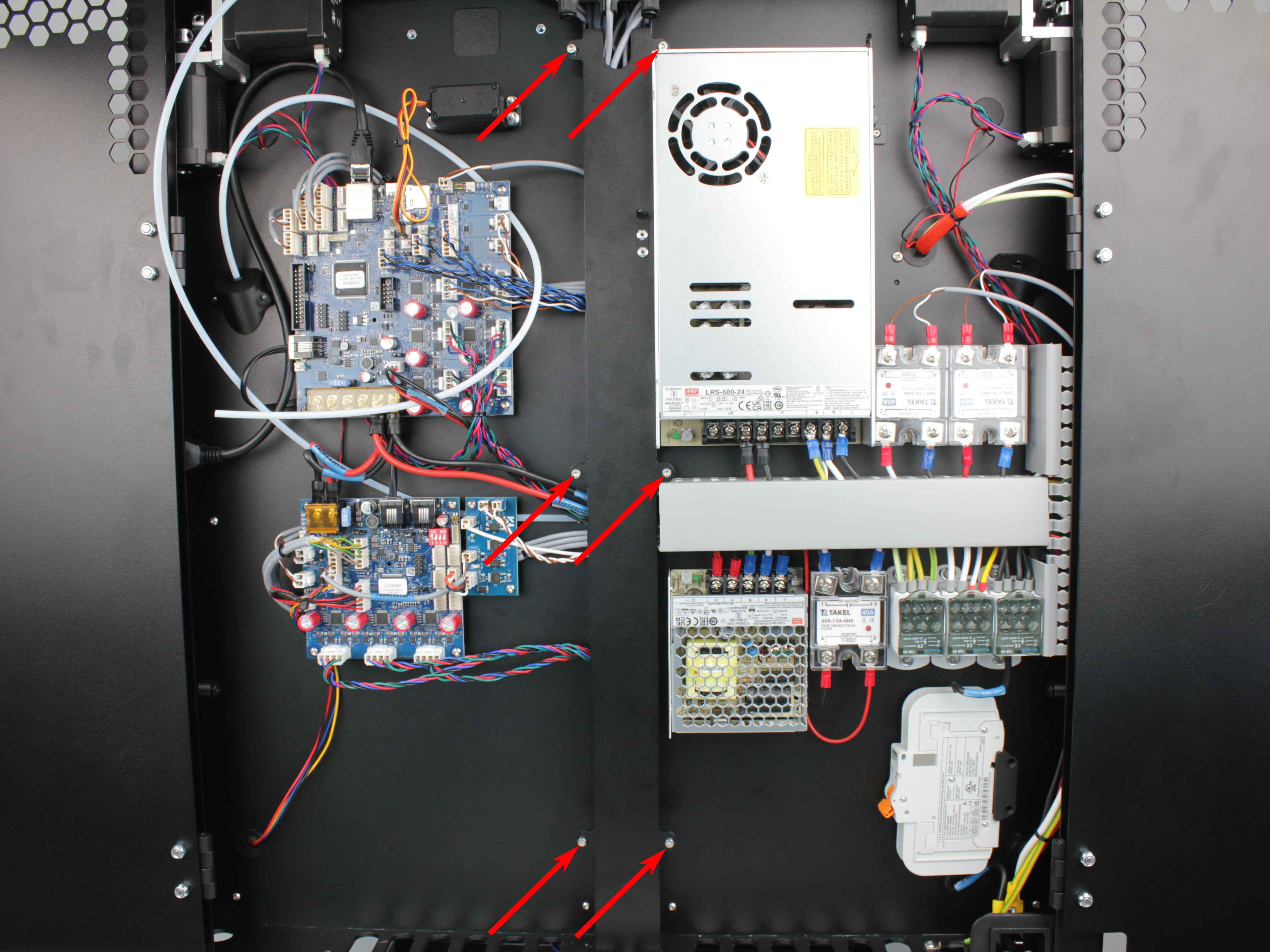
- Using the 2.5 mm hex screwdriver, remove all screws holding the wiring panel cover and carefully set the cover aside.
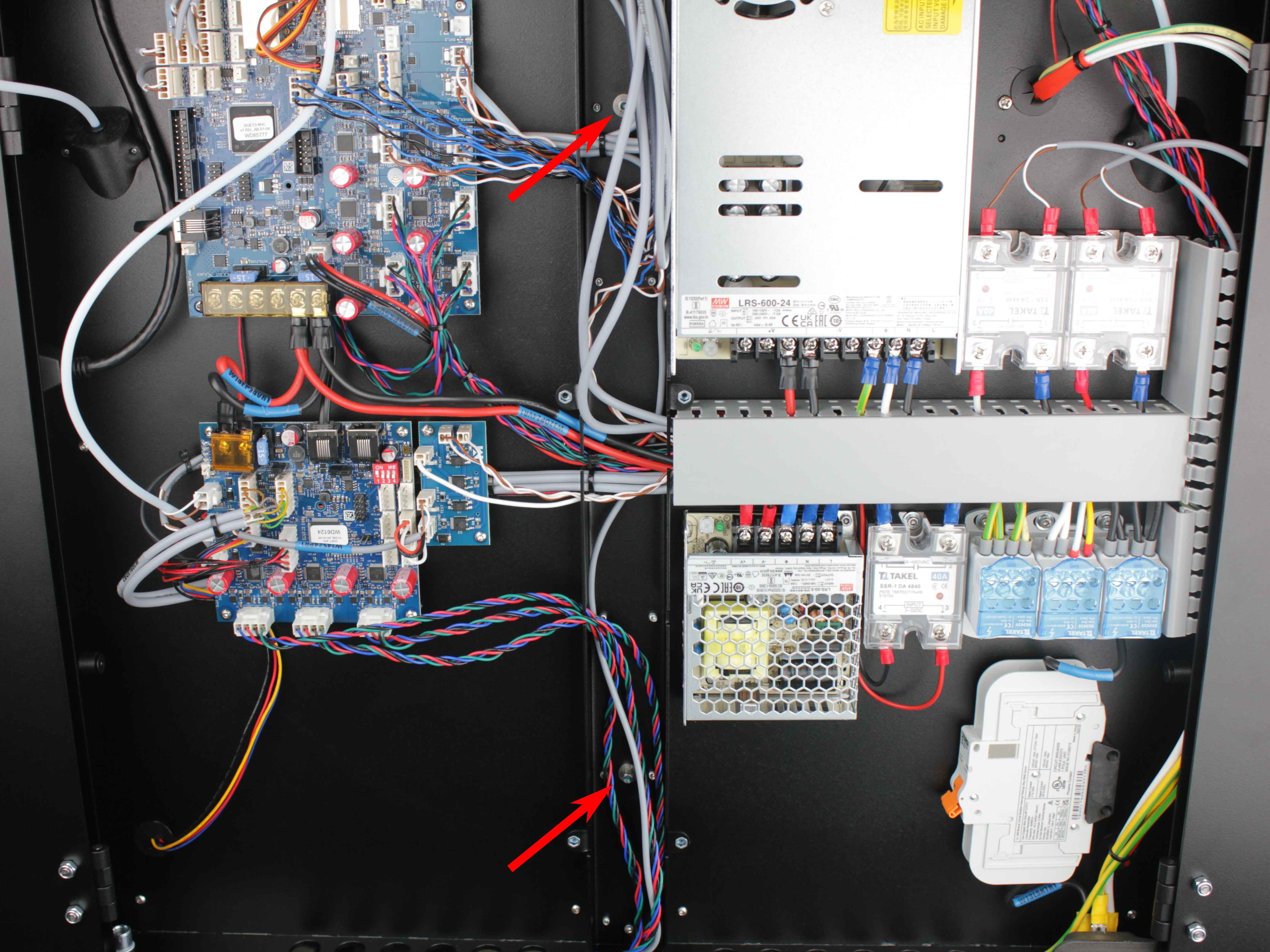
Support wires when removing panel
Be careful not to pull or strain any wires when removing the panel cover. If wires are routed through or attached to the panel, support them while removing it.
- Locate the two nuts or standoffs securing the back Z-rail.
- Hold each nut or standoff with the wrench – use a 5 mm wrench for standoffs (newer machines) or a 5.5 mm wrench for the older nuts – and tighten the screw from the other side with the 2.5 mm hex screwdriver.
- After tightening, re-check the back support with the wiggle test (step 10). There should be no play.
- Reinstall the wiring panel cover and secure it with the M3×6 screws.
- Run a test print to verify the Z-wobble is gone.
6. Z-Rail Retrofit Kit
Early Vision Miner 22IDEX V4 machines (serial number below 295) use standard nuts to secure the Z-rails. This configuration is prone to loosening over time and the threads can strip if over-tightened. Newer machines use an updated mounting design with standoffs and spherical washers.
Eligible customers can contact our support team to receive the updated Z-rail mounting kit as a free retrofit. Your serial number is located on the back of the red lid. For installation instructions, see Z-Rail Retrofit Kit Installation.
FAQ
Troubleshooting
Support
If you could not find an answer here, reach out to our support team.