Unboxing
This guide covers the complete unboxing and initial setup of the Vision Miner 22IDEX V4. Follow these steps after receiving your shipment to safely unpack the printer, install accessories, and prepare it for first use.
Before you begin - safety and risk
Read the Safety - Before You Begin article to understand the hazards involved in working on the Vision Miner 22IDEX V4 - including electrical, thermal, mechanical, and chemical risks. All procedures in this wiki are provided as recommendations only. By choosing to follow any procedure, you do so at your own risk.
Important unboxing precautions
Weight and handling: The crated printer weighs approximately 80 kg (≈ 175 lbs). Use a forklift, pallet jack, or at least two people for all lifting. Do not attempt to move the crate alone.
Inspect before opening: Check the crate exterior for shipping damage. If you find significant damage, photograph it and report to Vision Miner and the carrier before proceeding.
Power requirements: Connect only to a properly grounded outlet rated for 20 amps. Never defeat or bypass the ground lead.
Save packing materials
Keep the shipping crate and all packing materials. You will need them if the printer ever needs to be shipped for service.
Video Guide
Watch our complete unboxing guide.
Tools and Materials
- Screwdriver or drill with Philips PH2 bit
- Utility knife
- 2 mm Hex screwdriver (hex wrench) - for touchscreen installation
- Side cutters (flush cutters) - for cutting zip ties
- Two or more people for lifting
Unboxing
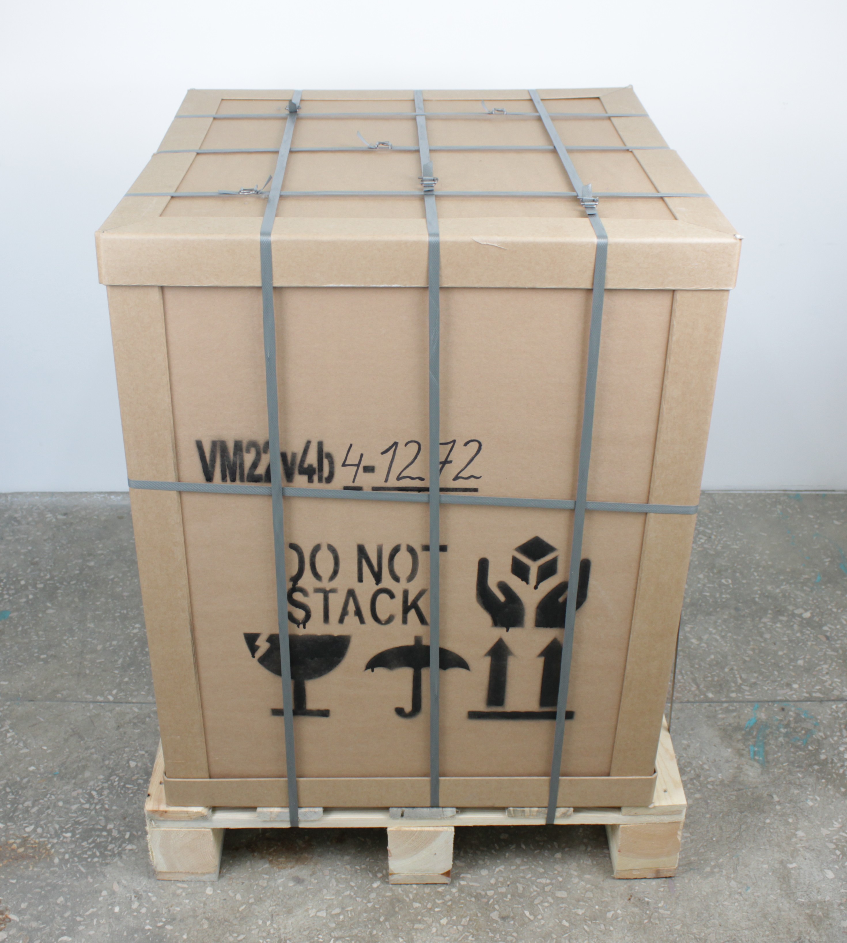
- Inspect the shipping crate for damage. The printer arrives wrapped in protective film.
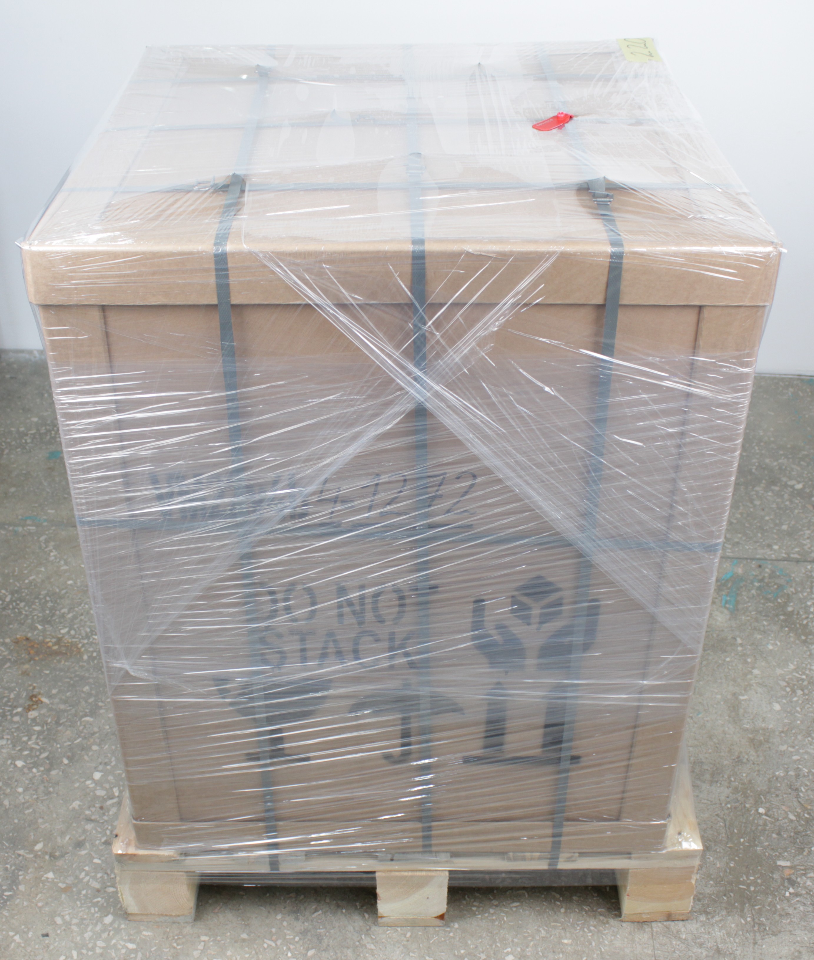
- Remove the outer protective wrap from the crate. The printer is secured with multiple straps.
- Remove the vertical straps, leaving one horizontal strap to keep the glass plates secured.
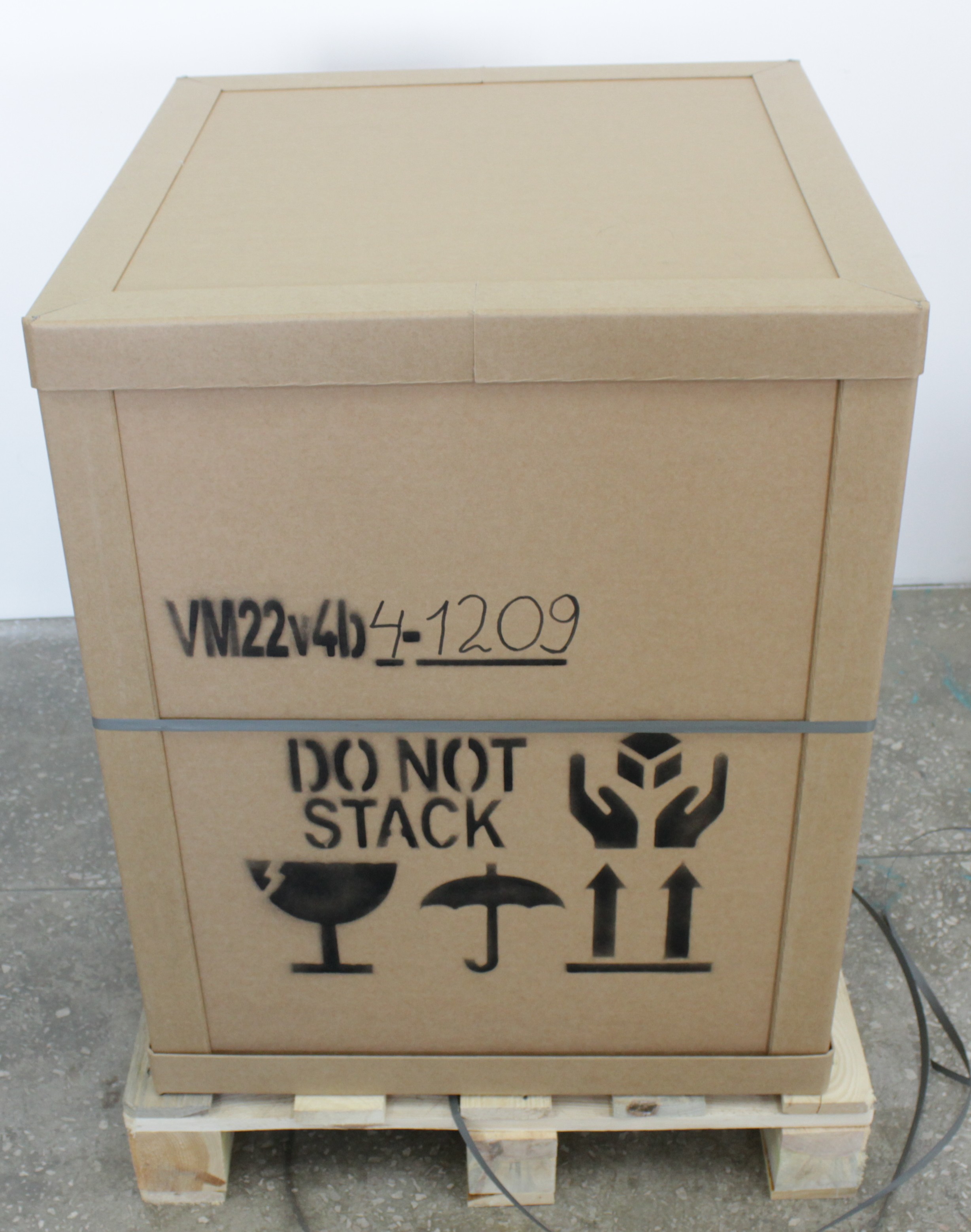
- Remove the top panel of the shipping crate.
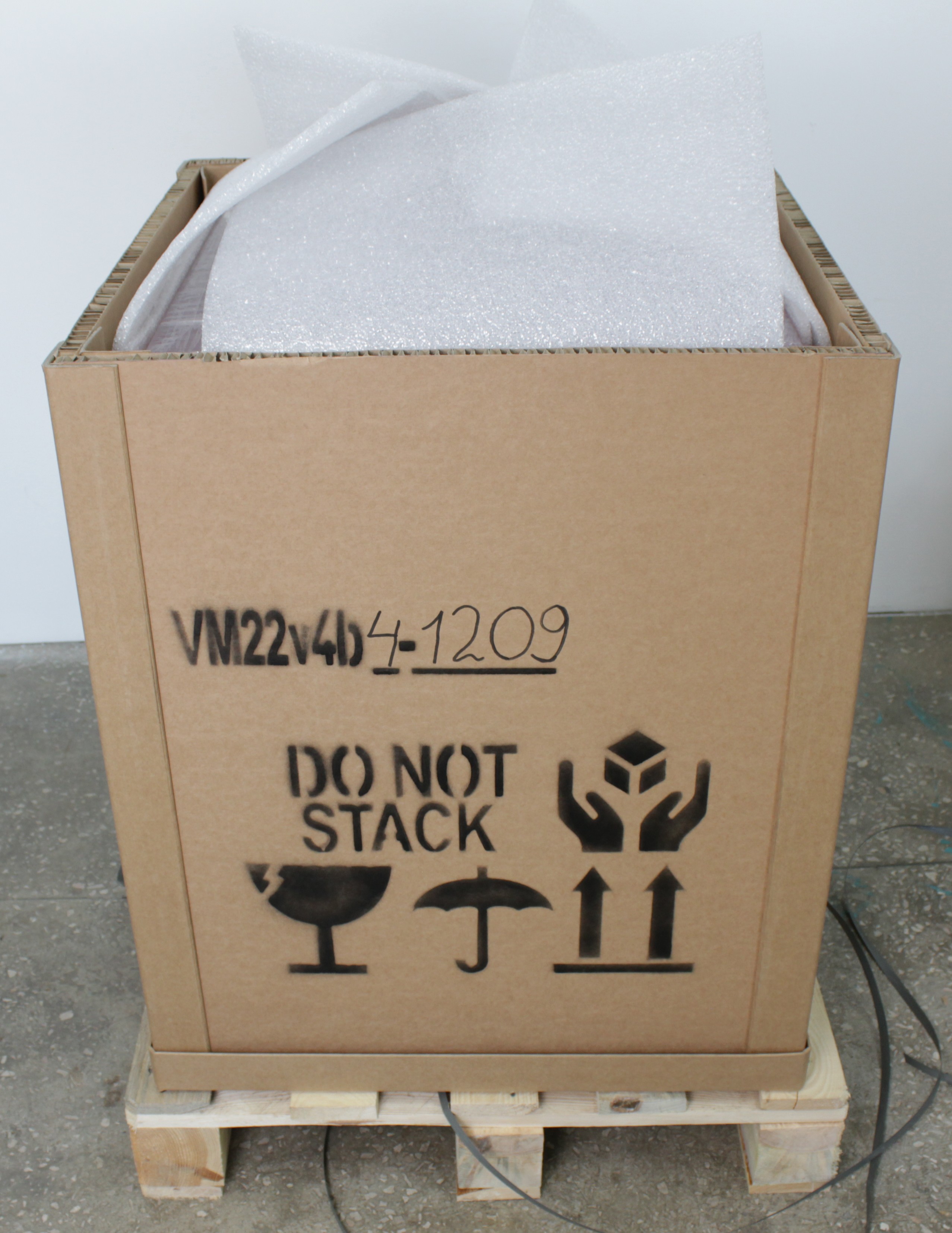
- Carefully lift the outer box straight up with at least two people. Slide it up vertically to avoid scratching the printer. Remove the foam packing material.
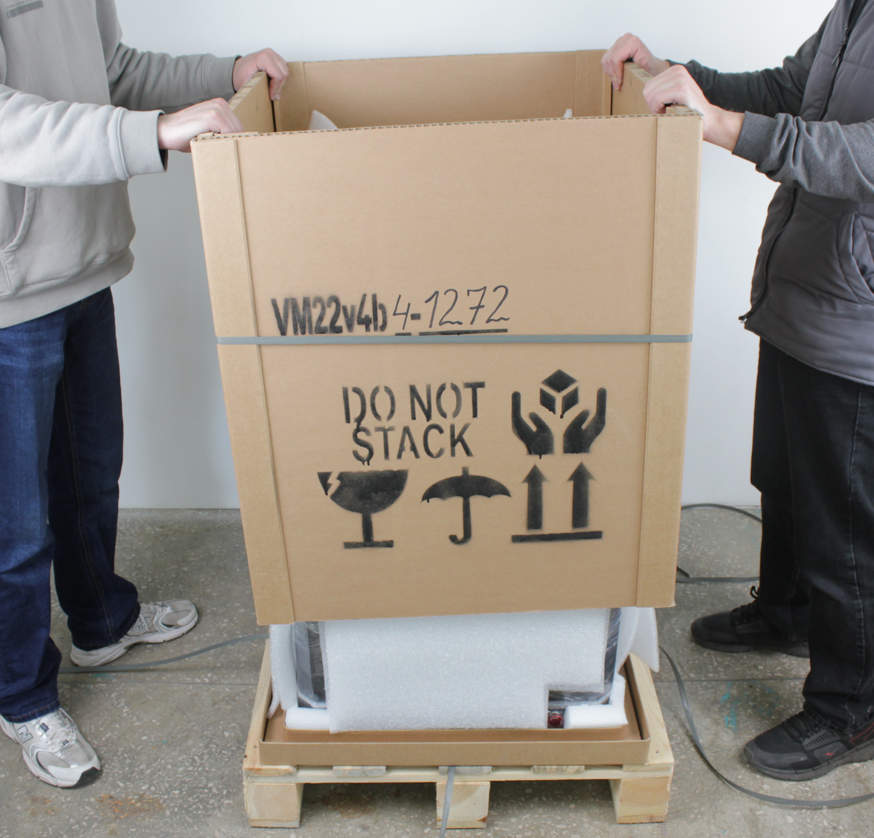
- The printer is now visible, still wrapped in protective plastic and secured with straps inside the crate.
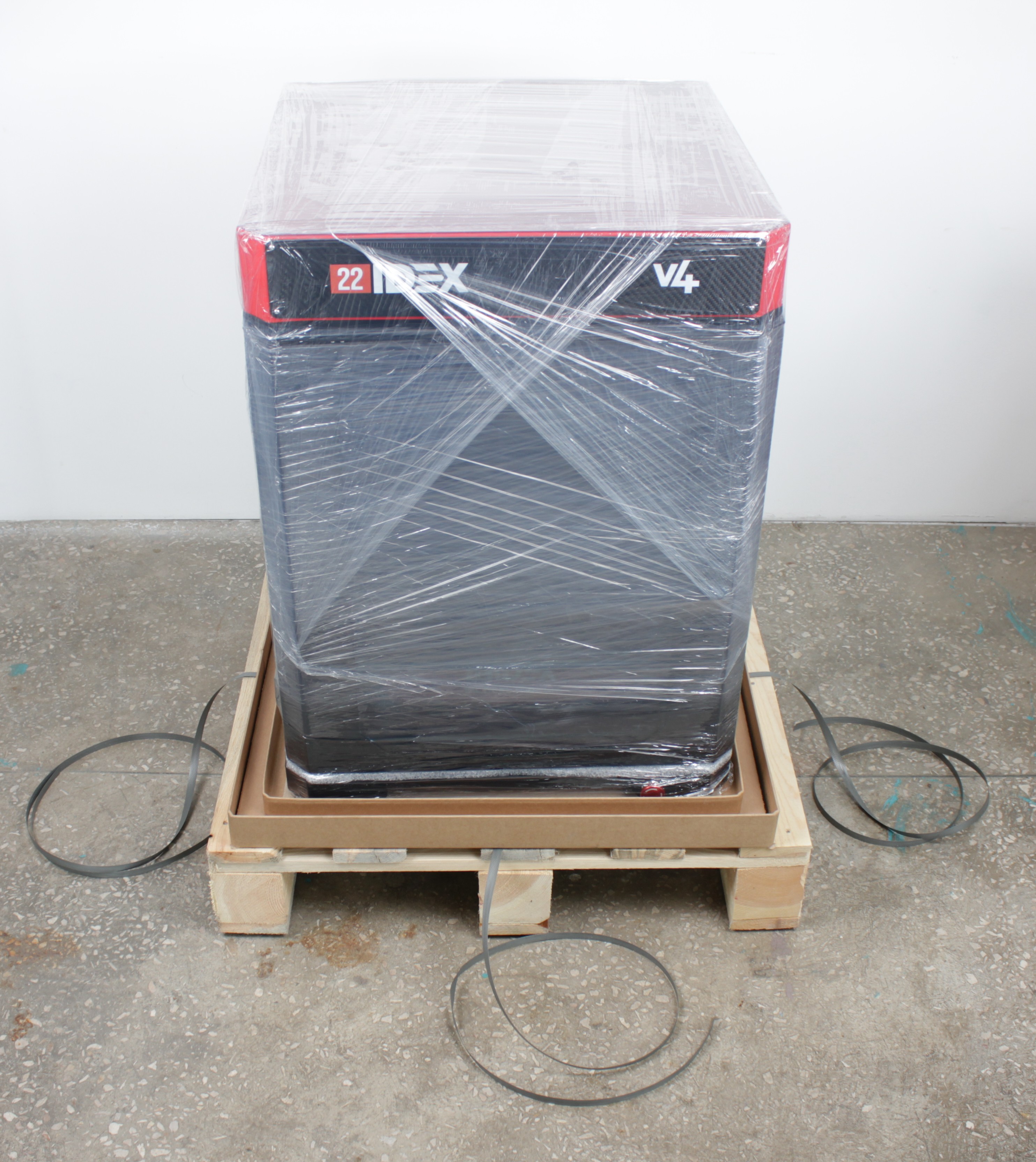
- Remove the plastic wrap and cut the remaining straps from the printer.
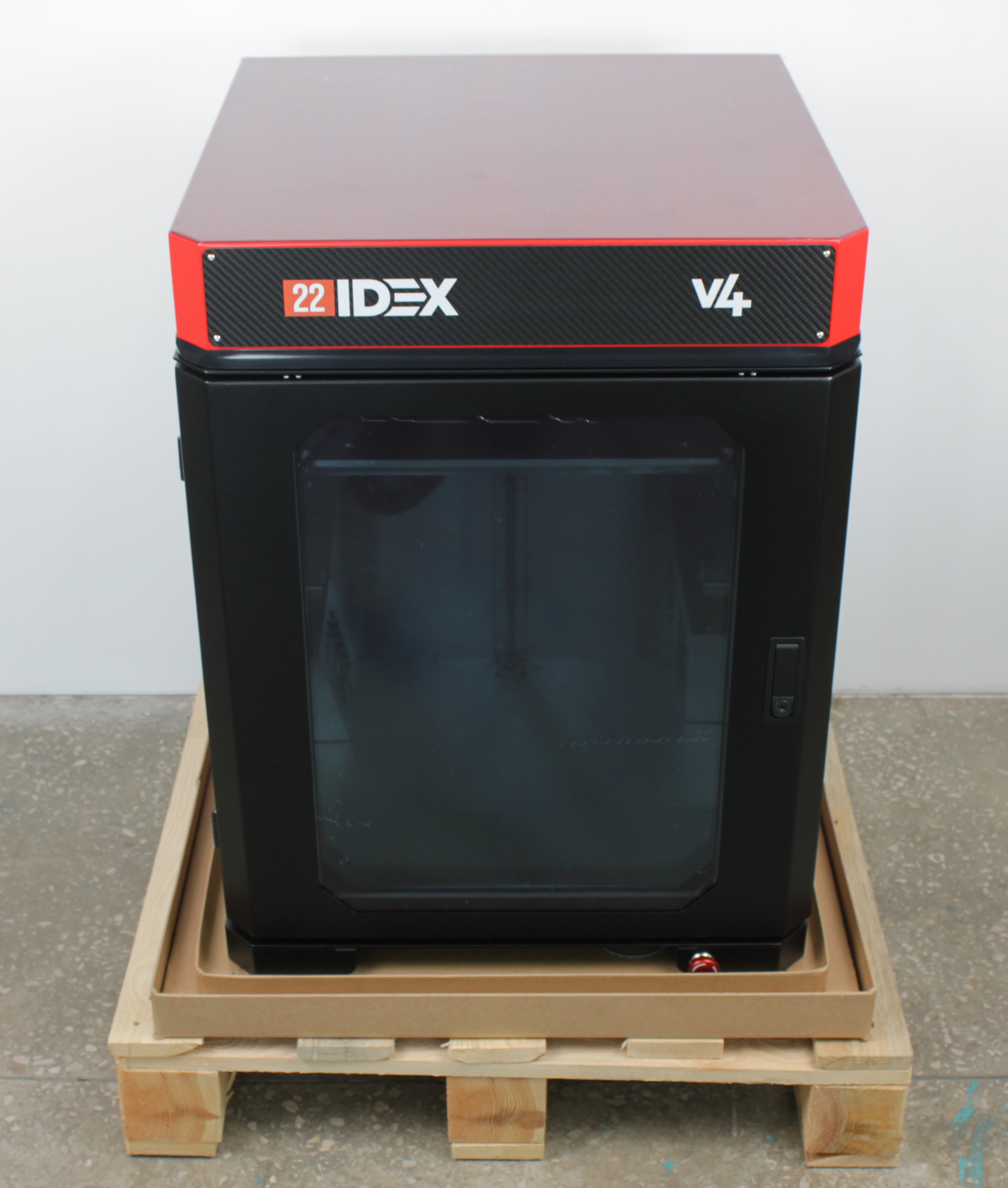
Positioning the Printer
- Lift the printer with at least two people and place it on a stable, level surface that does not wobble or rock. The surface must support at least 80 kg (≈ 175 lbs).
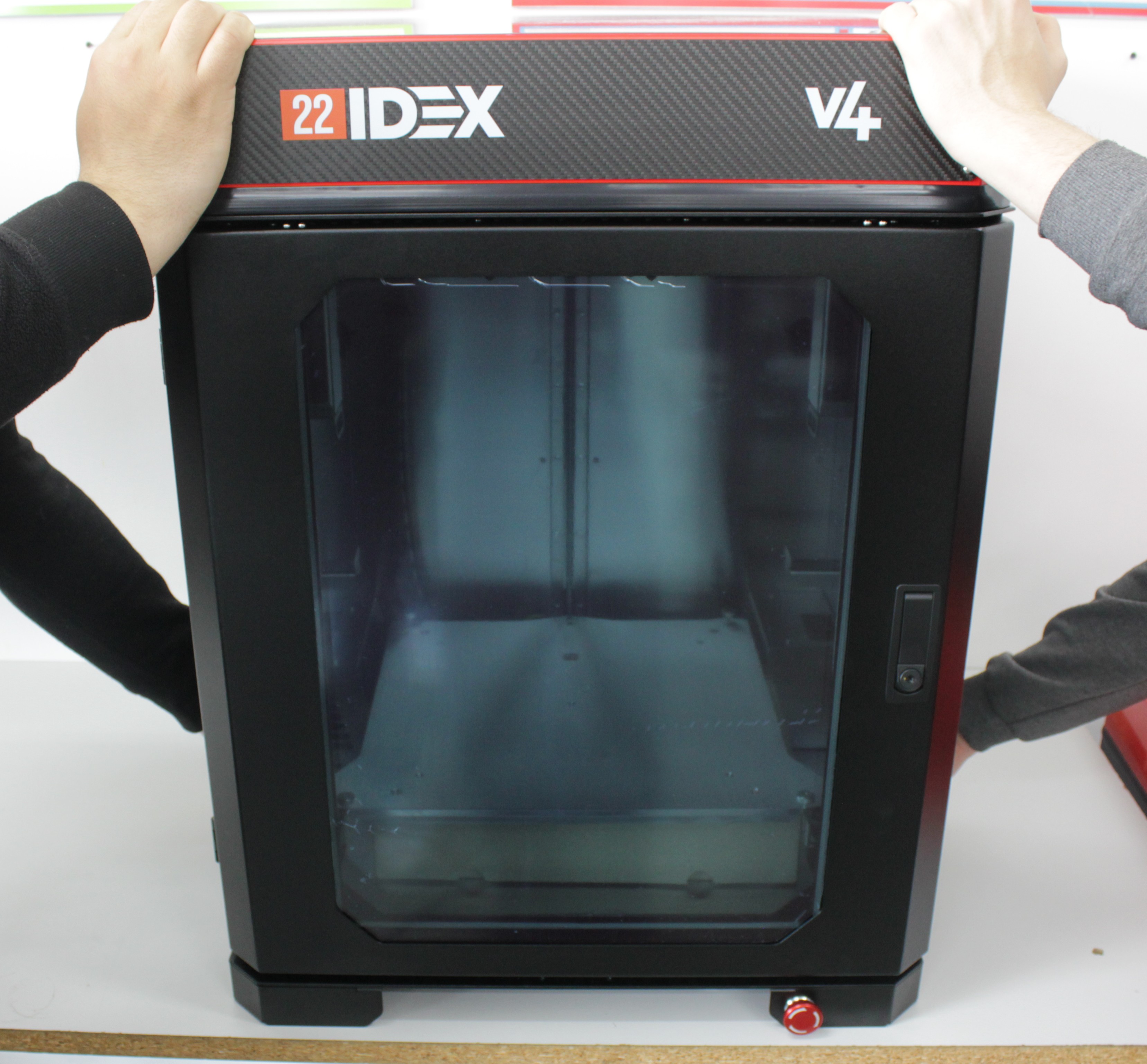
- Provide at least 150 × 150 cm (≈ 60 × 60 in.) of space for the printer. Keep at least 50 cm (≈ 20 in.) of clearance on all sides, with enough room for the front and rear doors to open fully. Adjust the four leveling feet at each corner until the printer sits level on the surface.
Removing Transport Protection
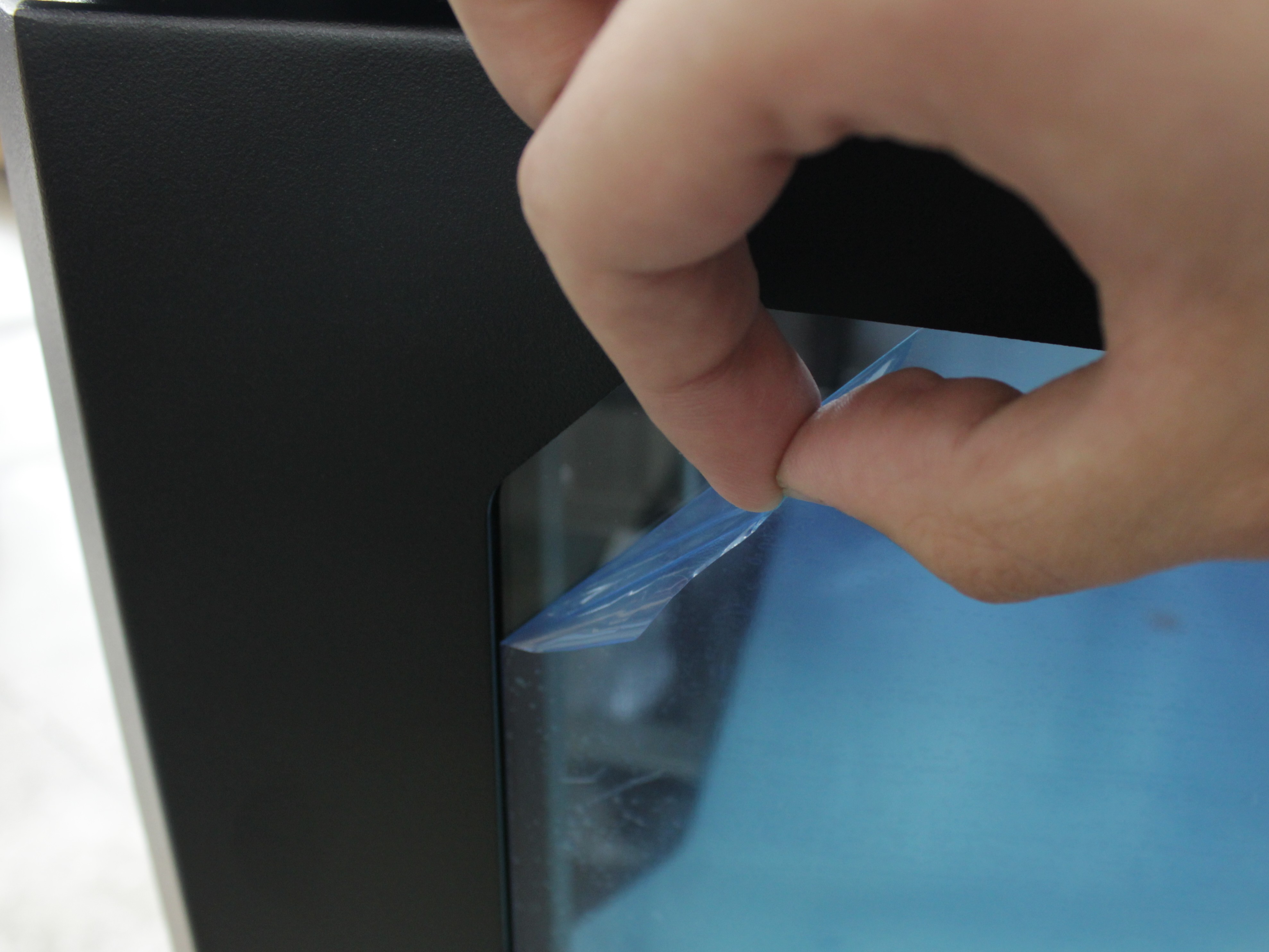
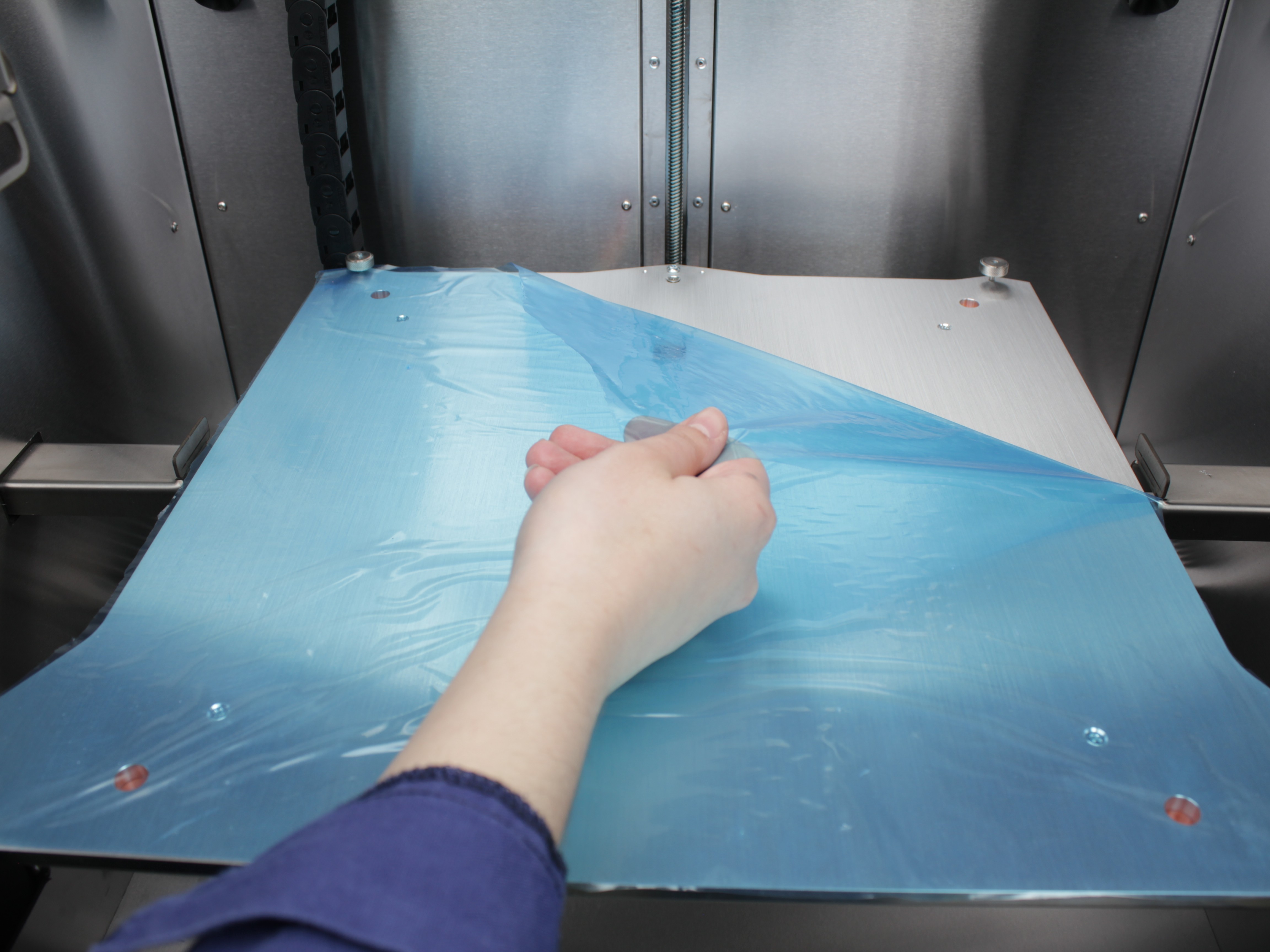
- Open the front door. Peel off the protective film from the door glass and from the build plate surface.
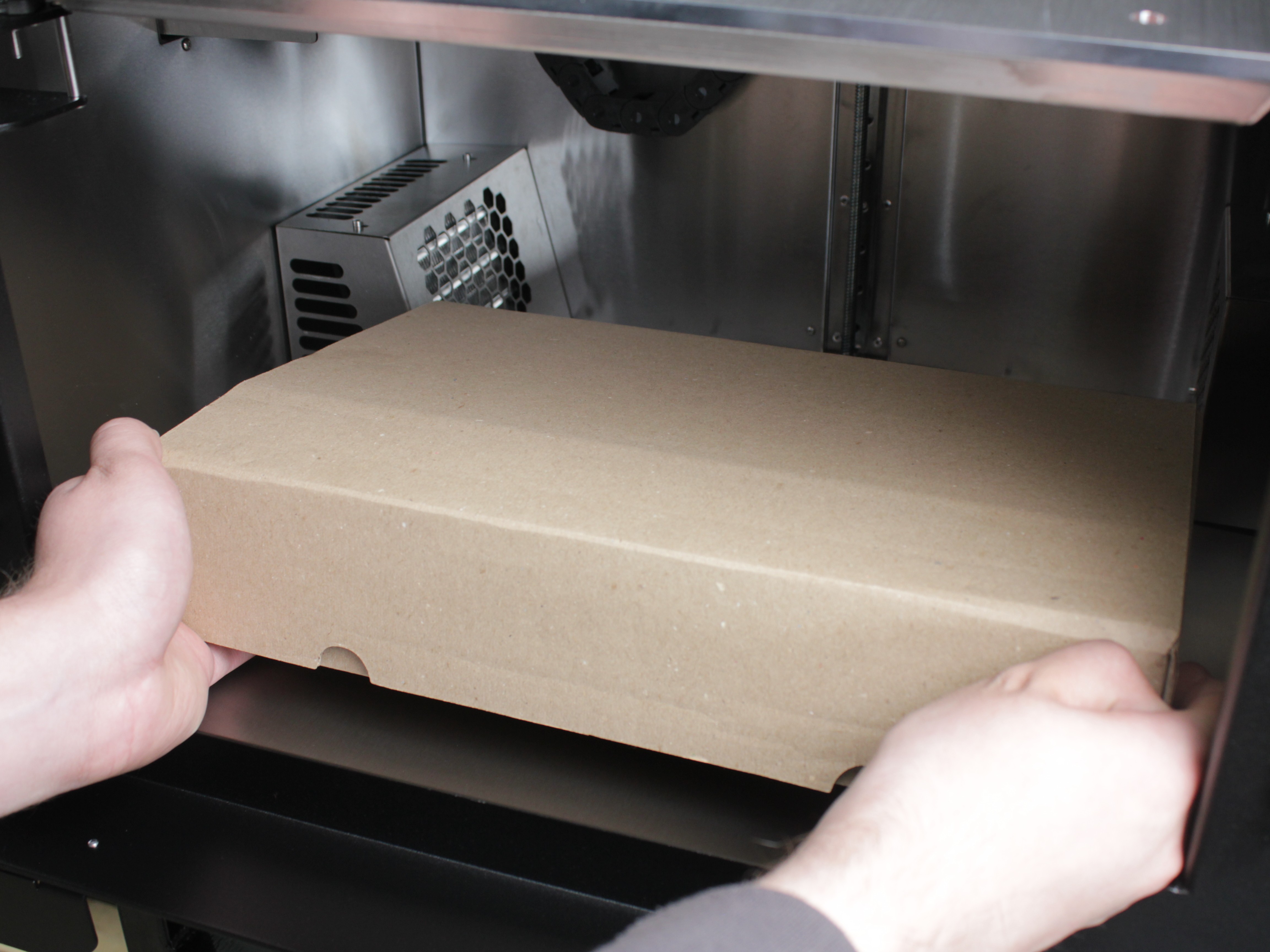
- Lift the build plate upward to access the compartment underneath. Remove the accessory box from inside the printer.
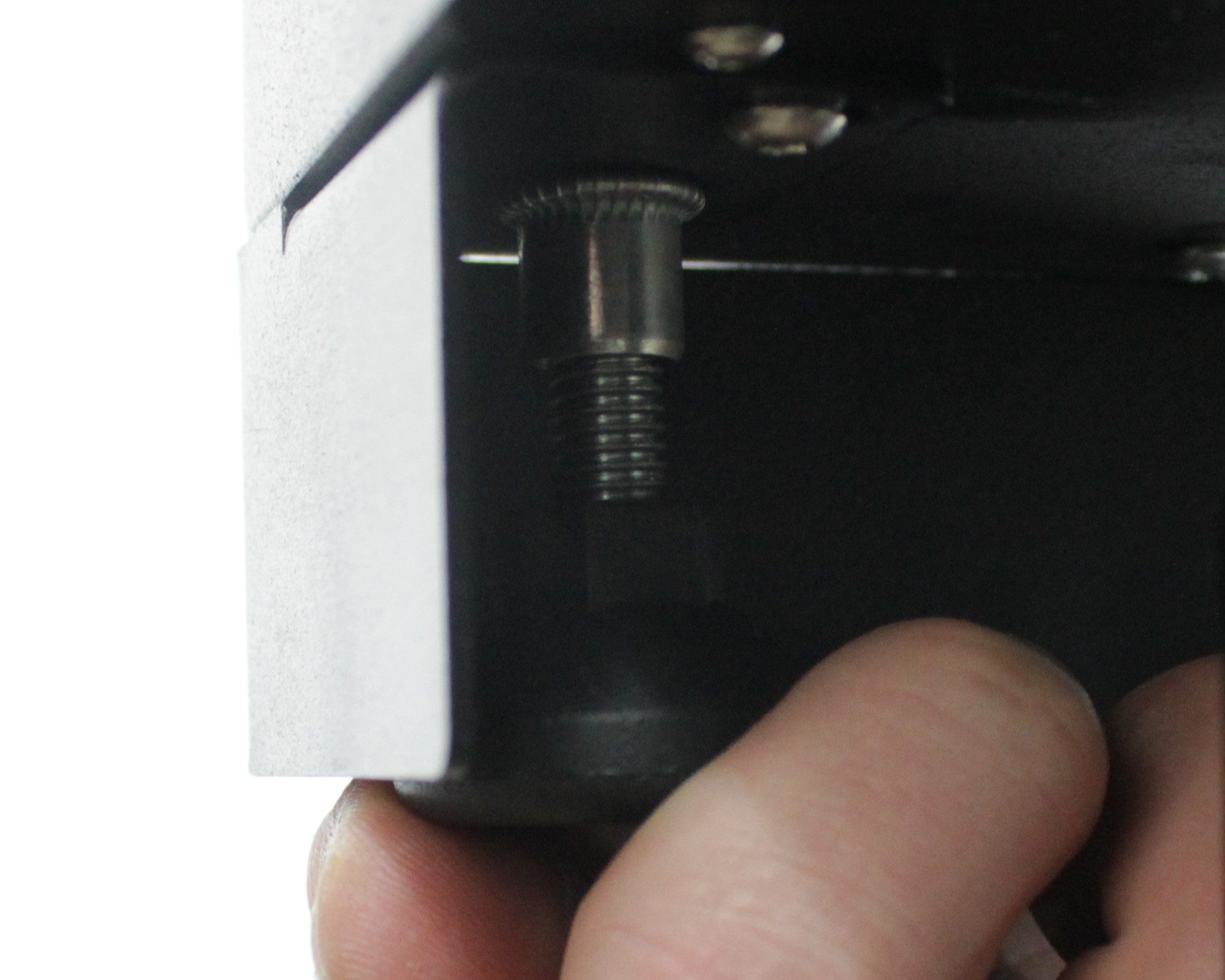
- Check the bed play at all three screw locations. Locate the three build plate securing screws: front left, front right, and rear center. Each screw passes through the build plate, threads into the build plate holder, and is secured from below with a nut. The screws prevent the build plate from falling off the holders, but they must not clamp the build plate down. The build plate should have 2-3 mm of upward play at each of the three screw locations.
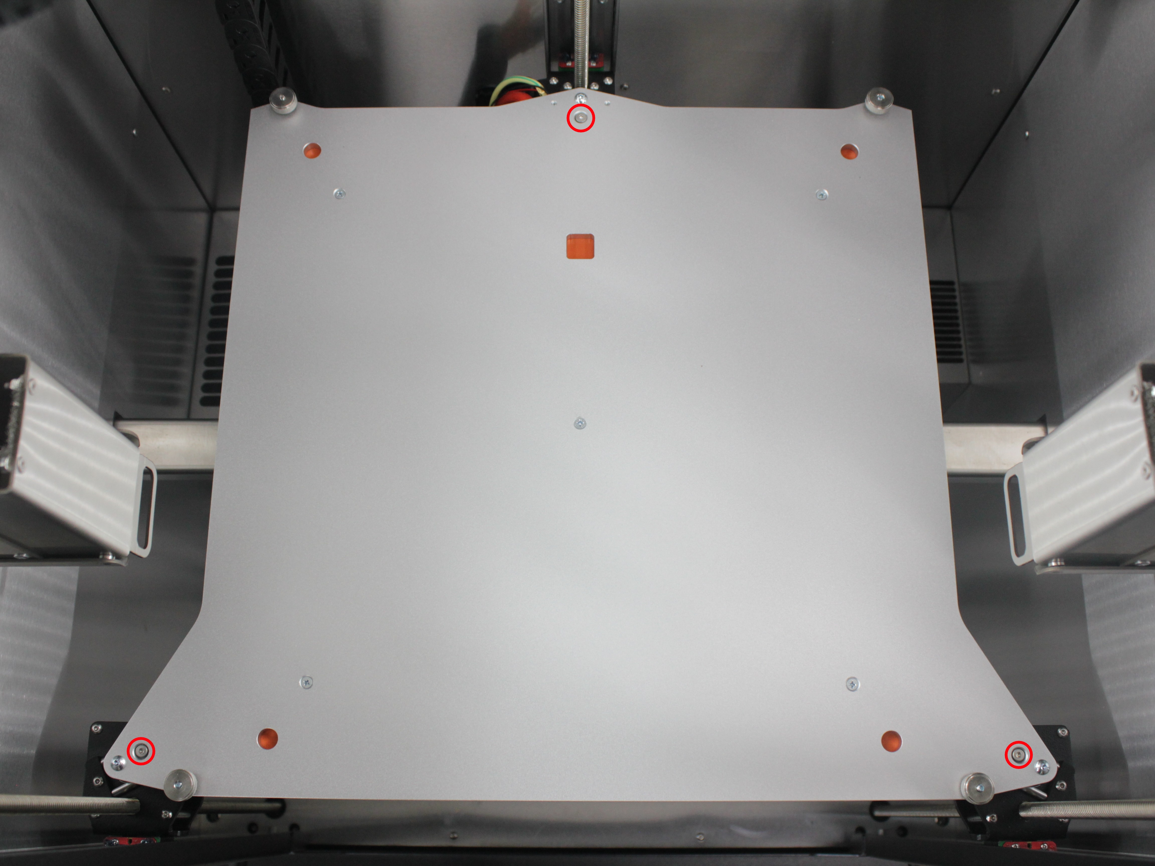
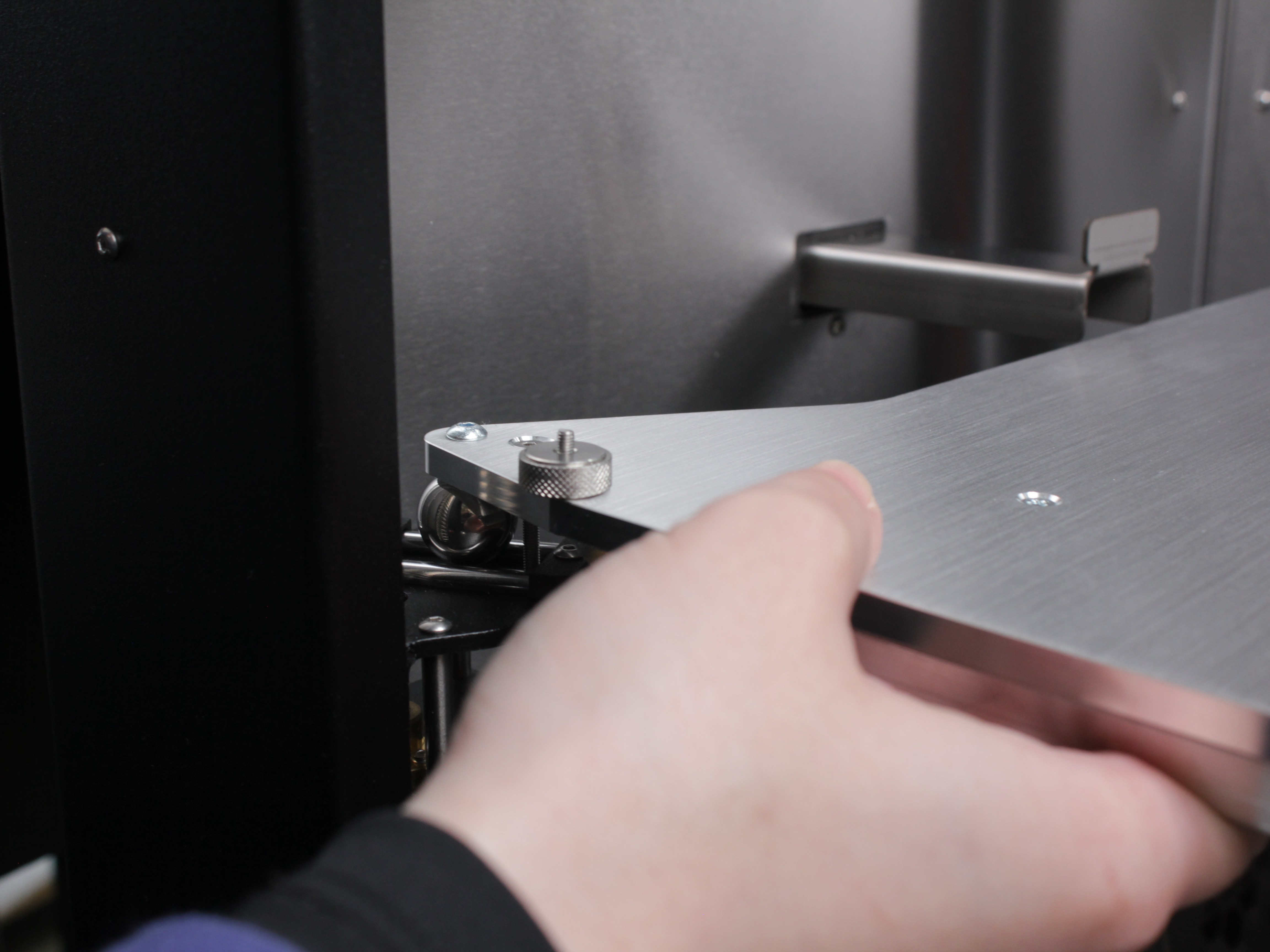
Gently lift the bed upward at each screw location:
- The bed should move up freely by 2-3 mm at each point.
- Verify that the rear center screw is flush with or slightly below the bed surface - if it protrudes, it will distort the bed mesh.
- If the bed moves freely upward at all three corners - the screws are set correctly from the factory. Proceed to the next step.
- If the bed is locked or has no upward play - the screws are still tightened for transport. For each screw: use a 2 mm hex screwdriver to hold the screw, use a 5.5 mm wrench to loosen the nut from below, then unscrew the screw a few millimeters upward until the bed has 2-3 mm of upward play, and re-tighten the nut to lock the screw in this new position.
Bed must have 2-3 mm upward play
The bed must have 2-3 mm of upward play at each screw location for proper thermal expansion and auto-leveling. Do not remove the screws completely - they serve as a safety stop to prevent the bed from detaching. See Build Plate Securing Screws for details.
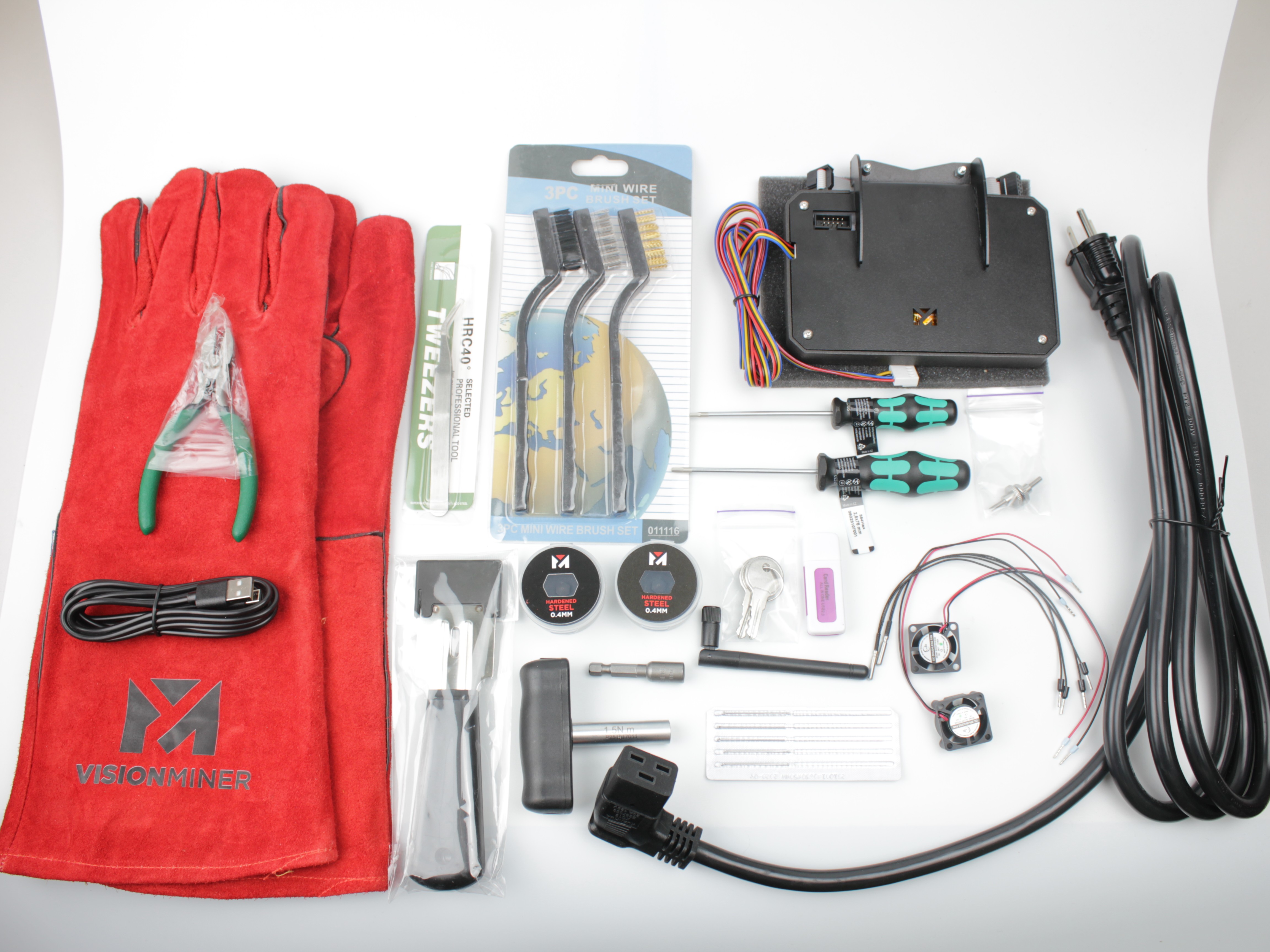
- Open the accessory box and verify that all included parts are present. Check the contents against the list below:
| Category | Item | Quantity |
|---|---|---|
| Tools | 2.5 mm Hex screwdriver (hex wrench), Wera | ×1 |
| 2 mm Hex screwdriver (hex wrench), Wera | ×1 | |
| Wire Cutters | ×1 | |
| Part Removal Scraper | ×1 | |
| Nozzle Cleaning Brush | ×1 | |
| Stainless Steel Curved Tweezer | ×1 | |
| Nozzle Torque Wrench and 7 mm Socket | ×1 | |
| Spare Parts & Components | Hotend Cooling Fan 2510 | ×2 |
| Copperhead Heat Break | ×2 | |
| Nozzle (packaged) | ×2 | |
| Nozzle Cleaning Needle | ×5 | |
| Hotend Temperature Sensor | ×2 | |
| Lid Thumb Screw | ×2 | |
| Electronics & Accessories | Touchscreen | ×1 |
| WiFi Module | ×1 | |
| microSD to USB Card Reader | ×1 | |
| USB-C to USB-A Cable | ×1 | |
| Power Cord | ×1 | |
| Materials & Consumables | Grease | ×1 |
| Nano Polymer Adhesive | ×1 | |
| High-Temp Gloves | ×1 | |
| Build Surface | Carbon Fiber Build Plate | ×1 |
Contact support if any part is missing or damaged
If any part is missing or damaged, contact support team before proceeding.
- Locate the 4 red transport zip ties securing the belts. Cut each zip tie carefully with side cutters to avoid damaging the belts:
- Two zip ties secure the crossbar from the left and right sides
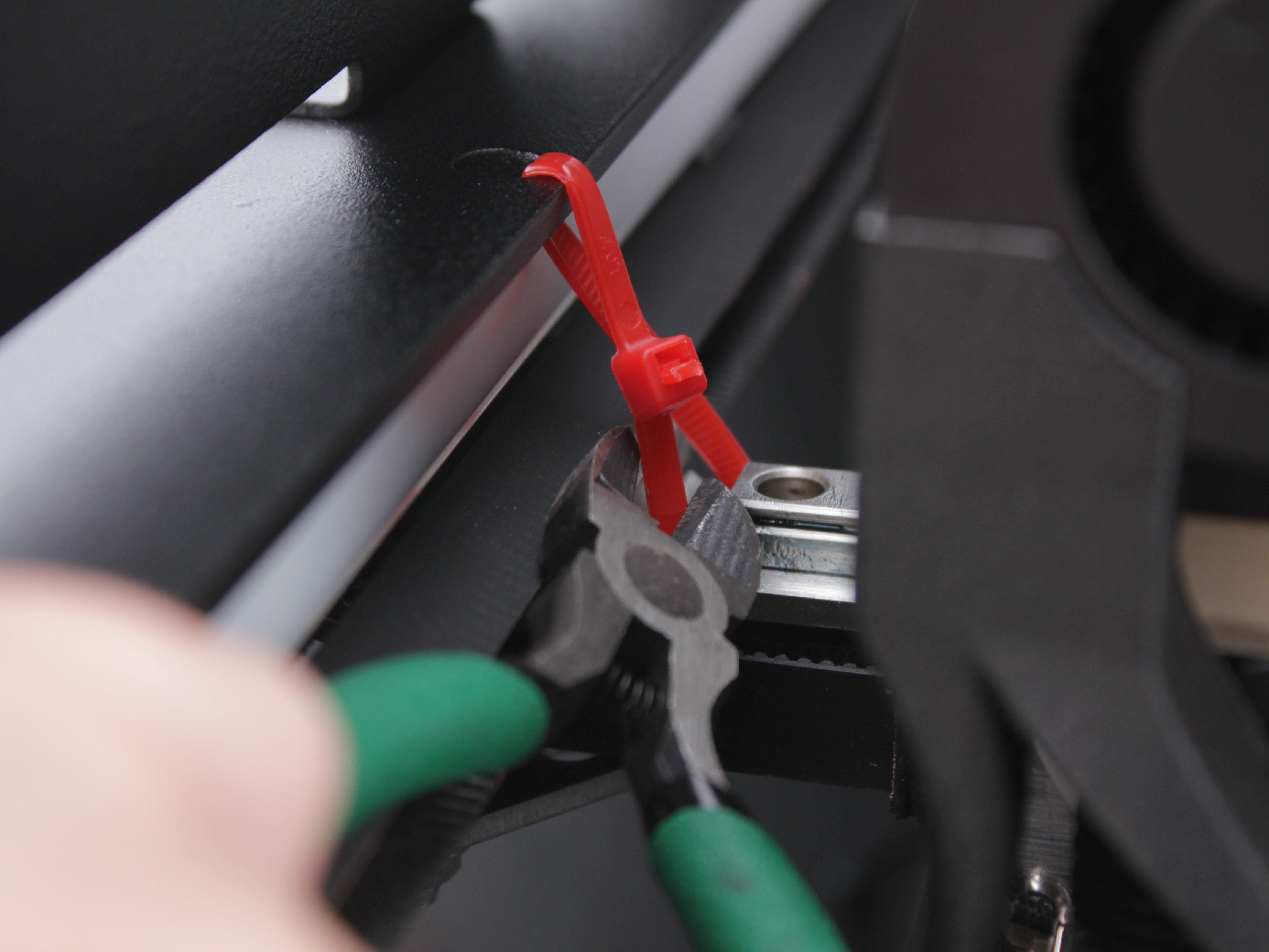
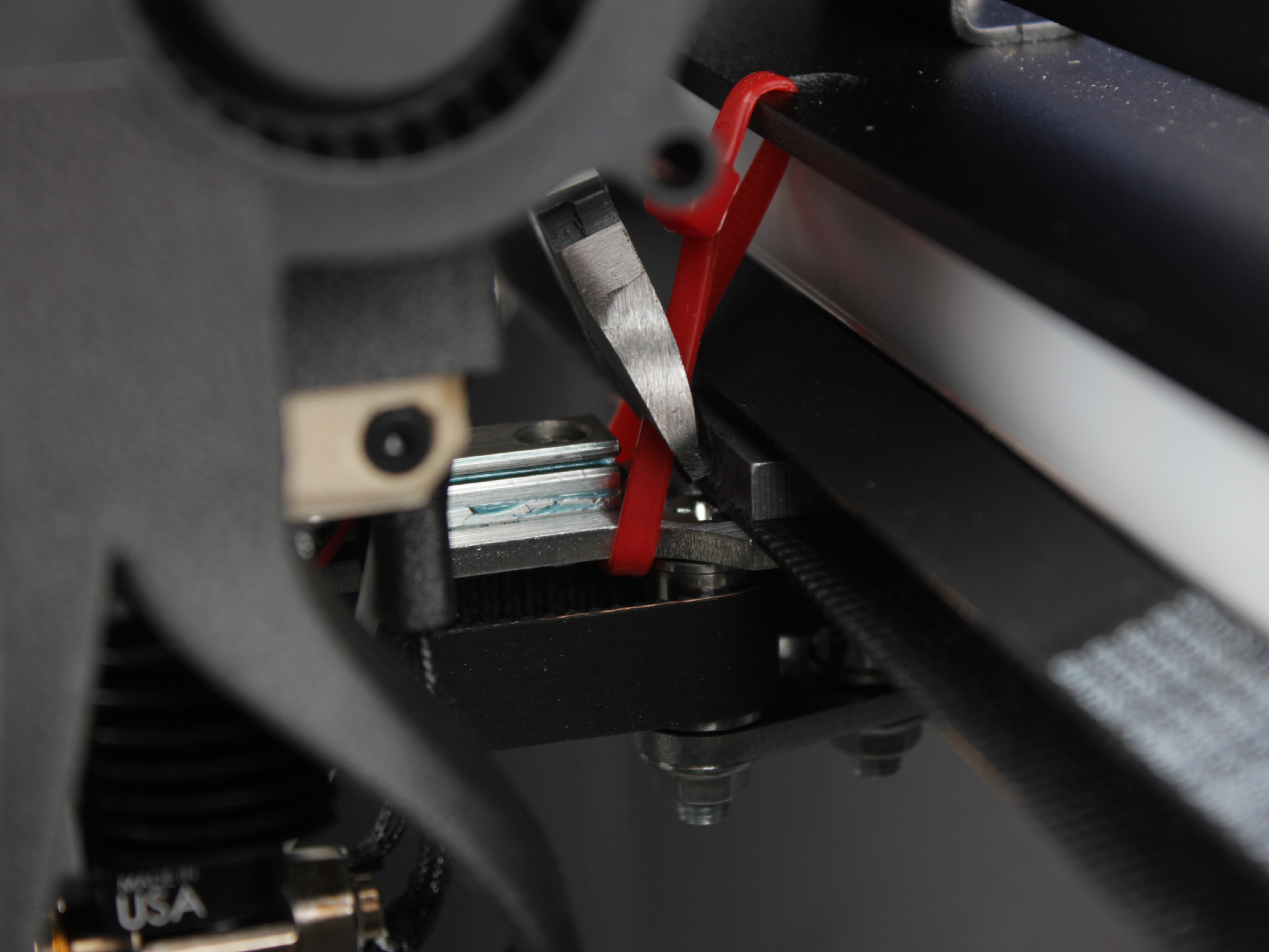
- Two zip ties secure the tool belts in the center of the crossbar
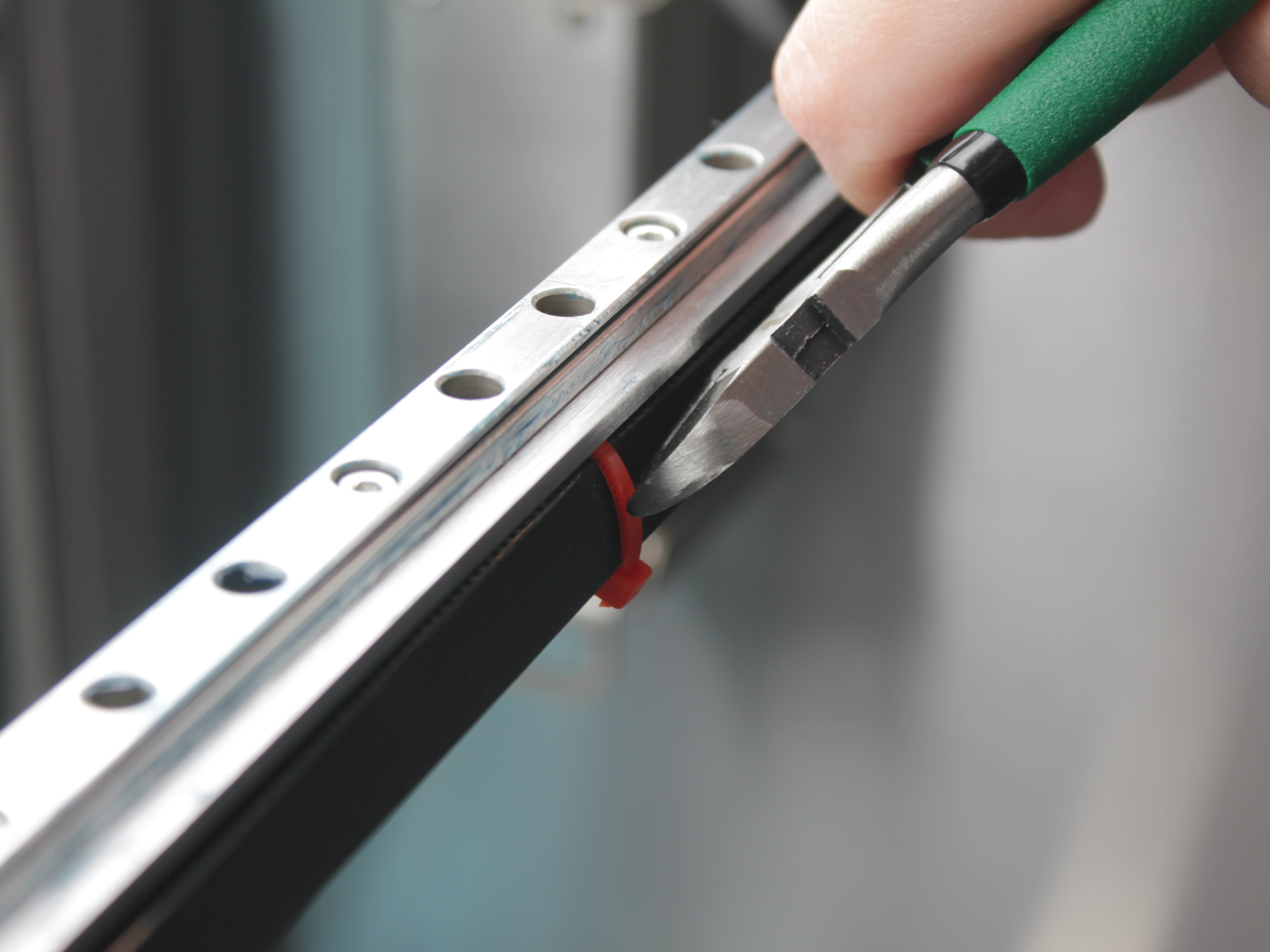
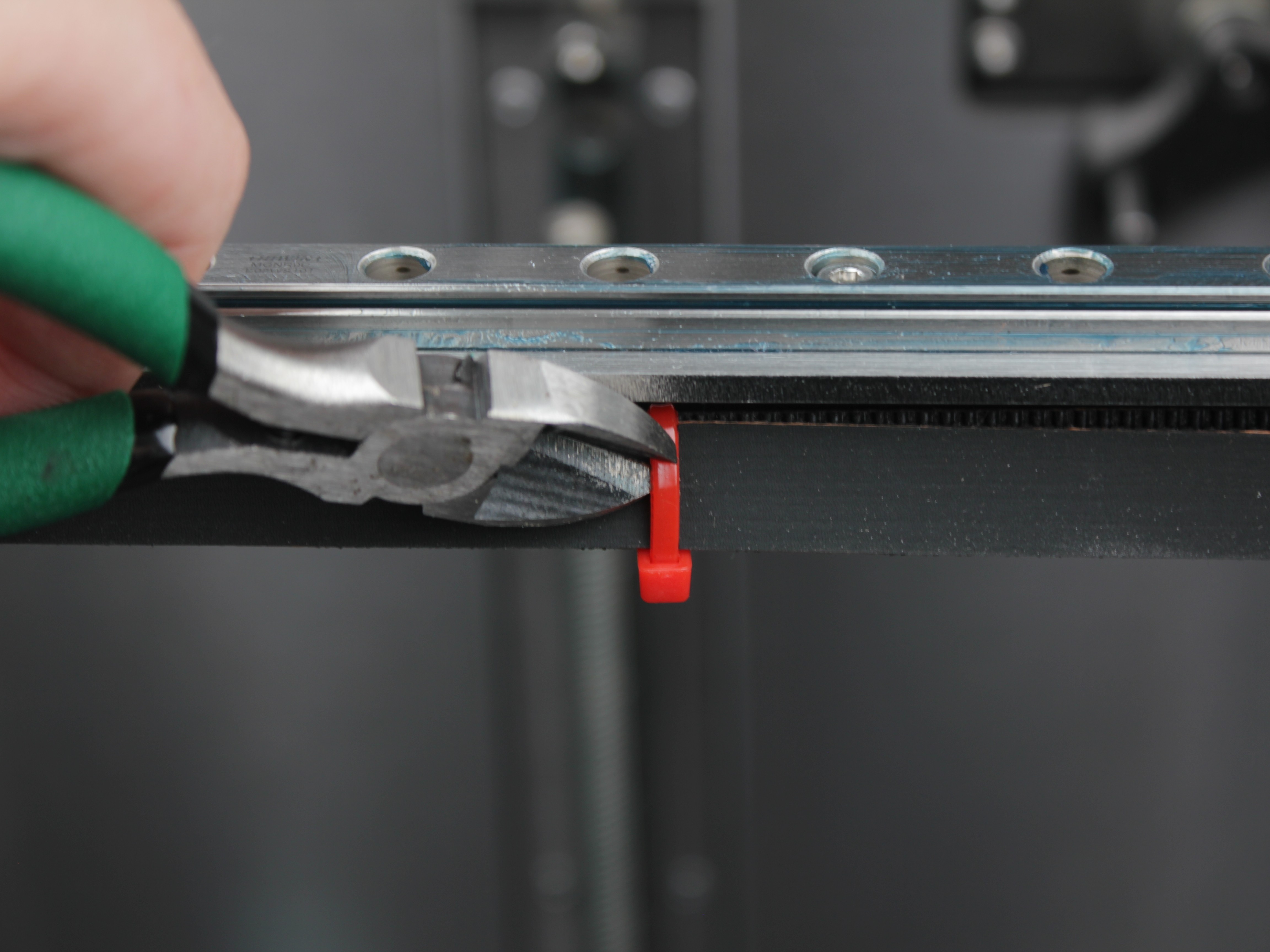
Cut zip ties carefully to avoid damaging belts
Cut carefully - do not nick or damage the belts.
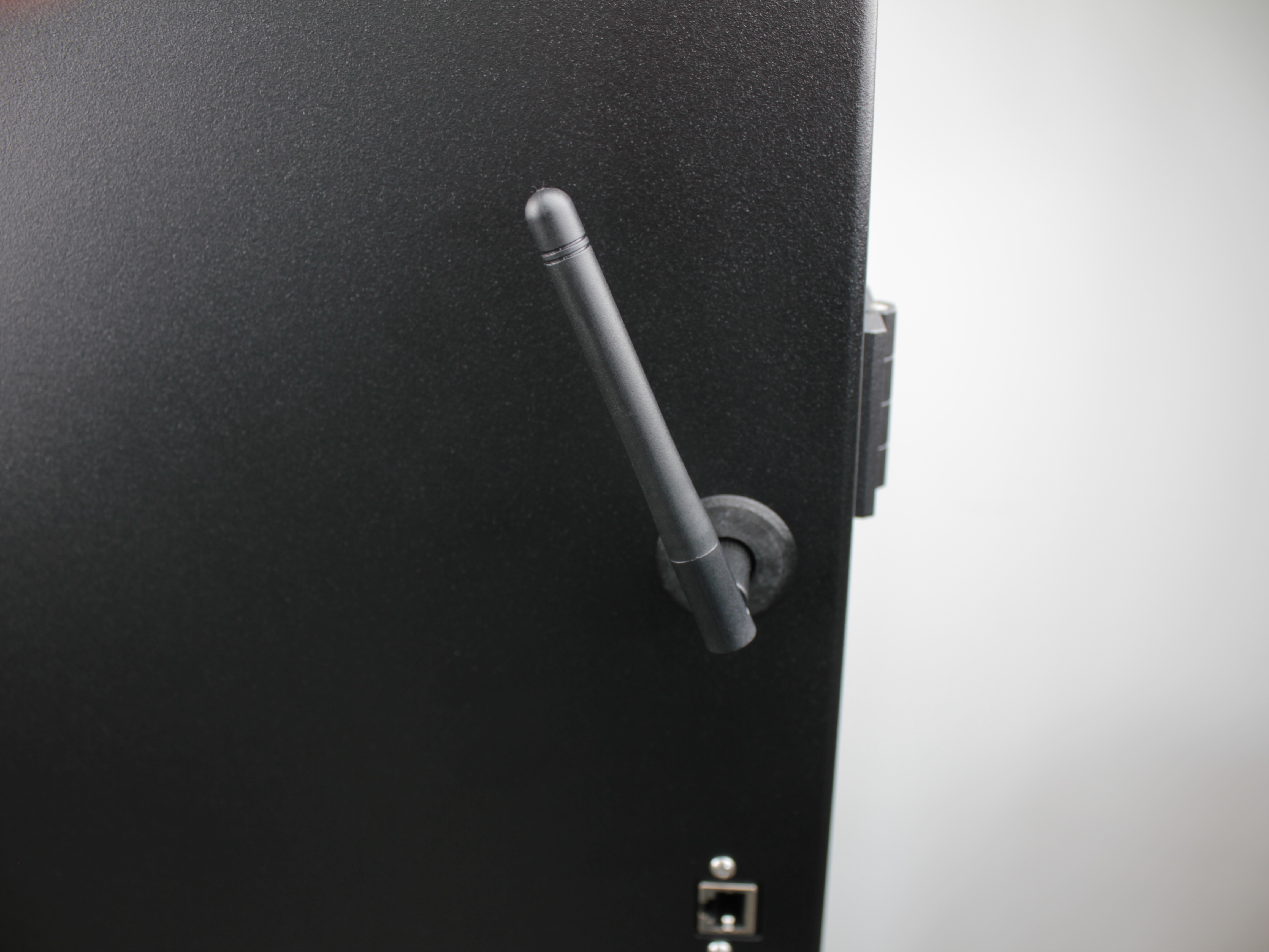
- Find the WiFi antenna in the accessory box. Screw it onto the antenna connector on the outside of the printer.
Installing Accessories
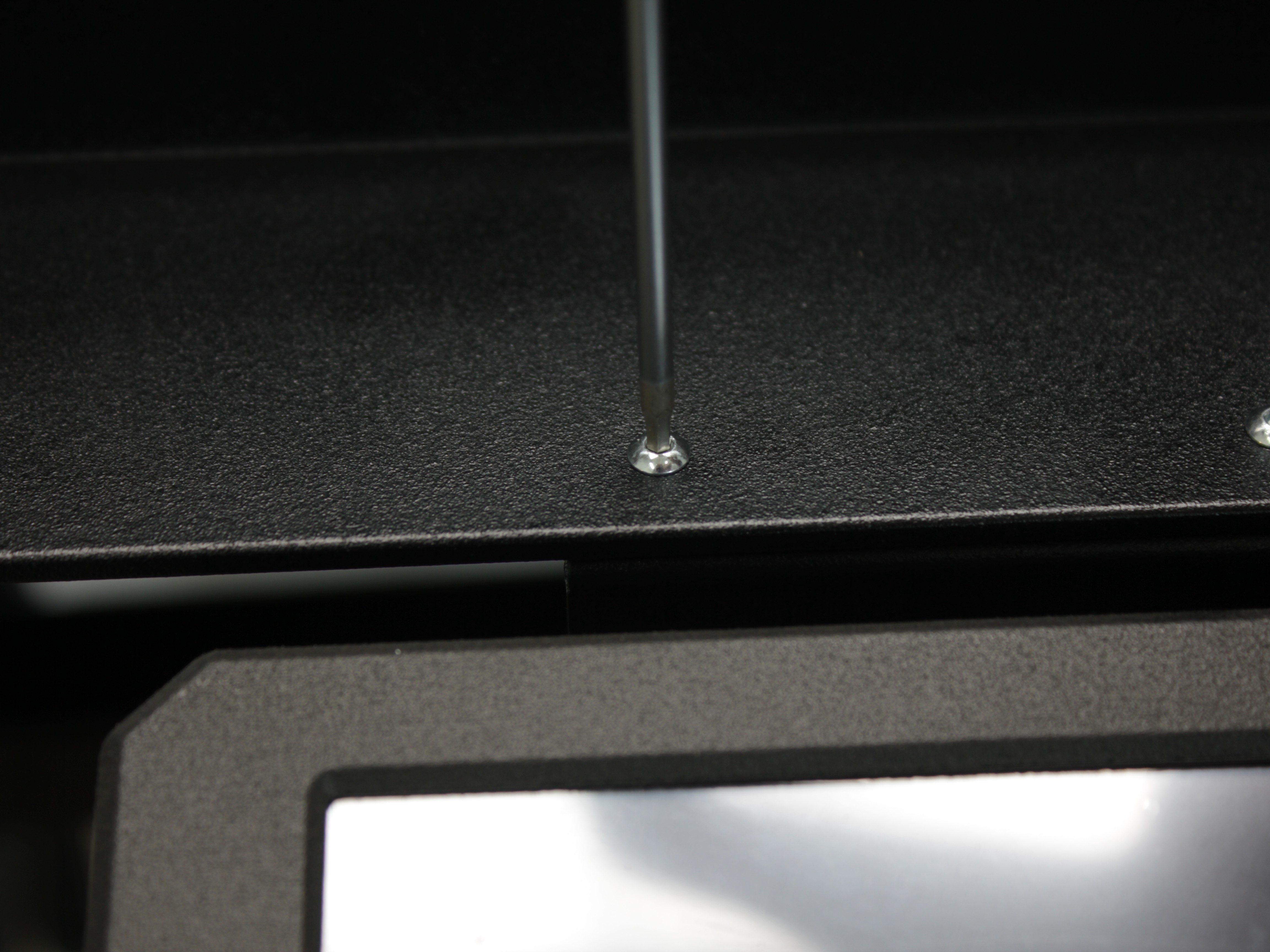
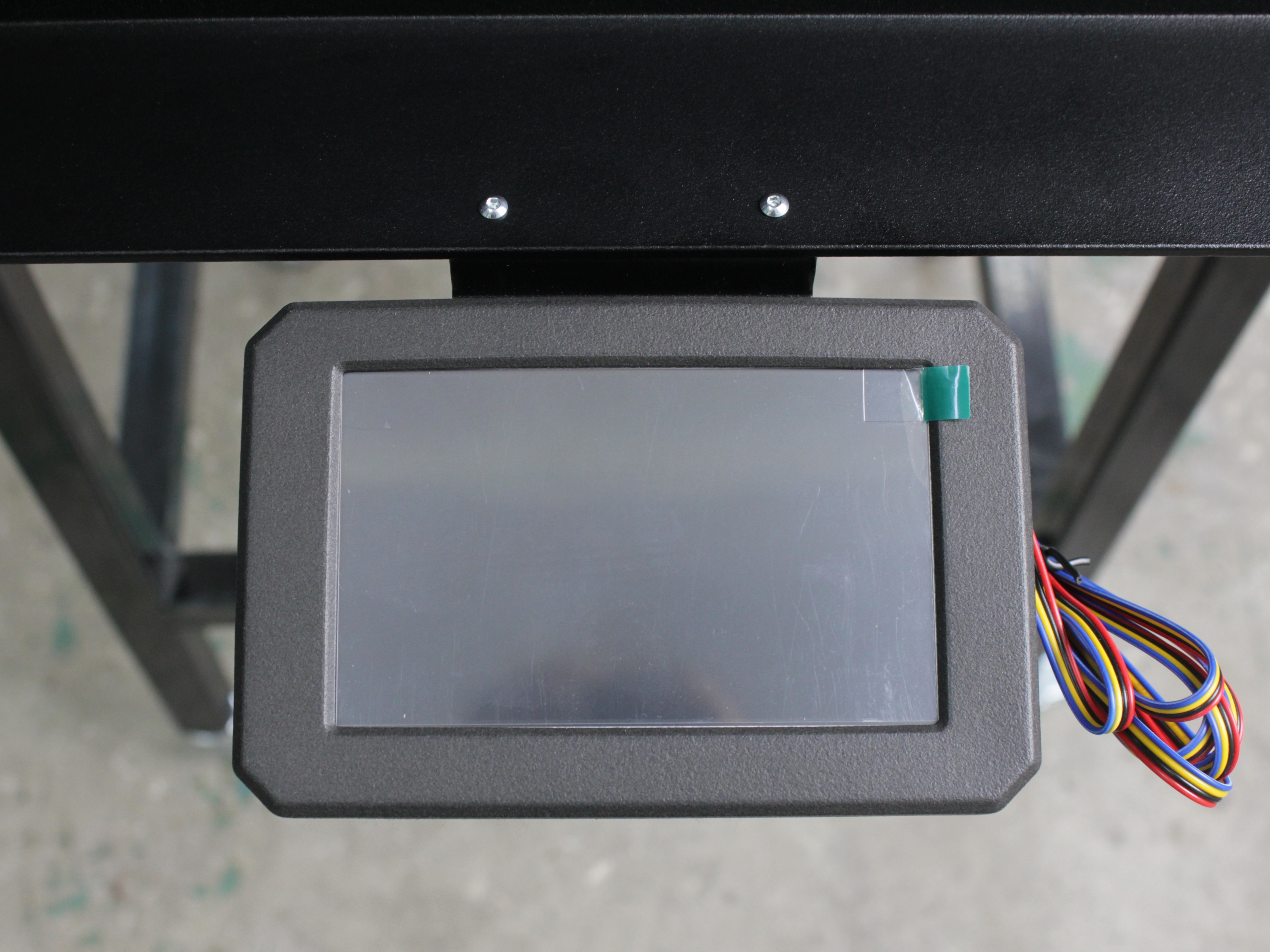
- Position the touchscreen from underneath, align it with the two mounting holes on the underside of the machine (front area), and secure with two screws from the top using the supplied 2 mm hex screwdriver.
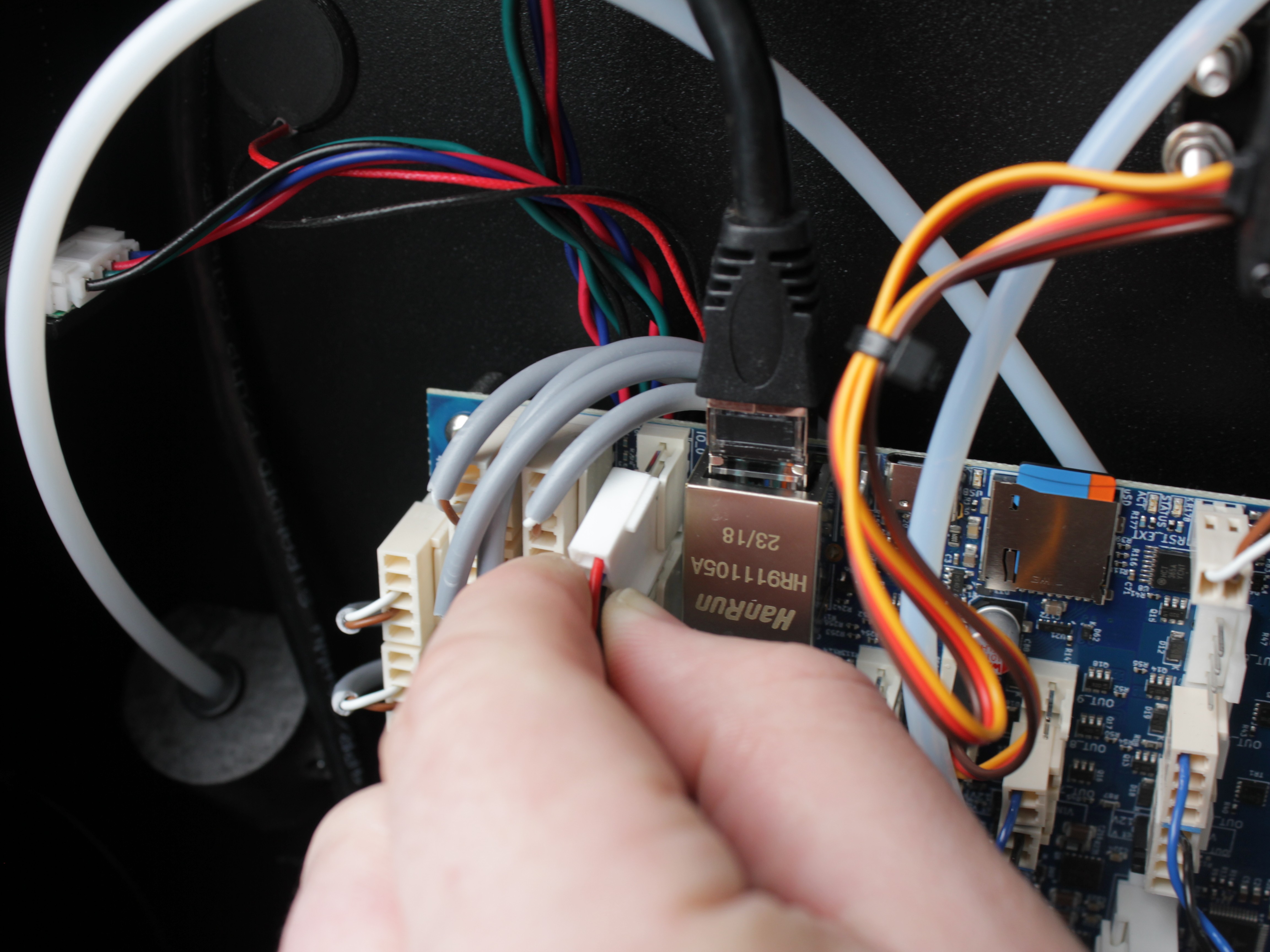
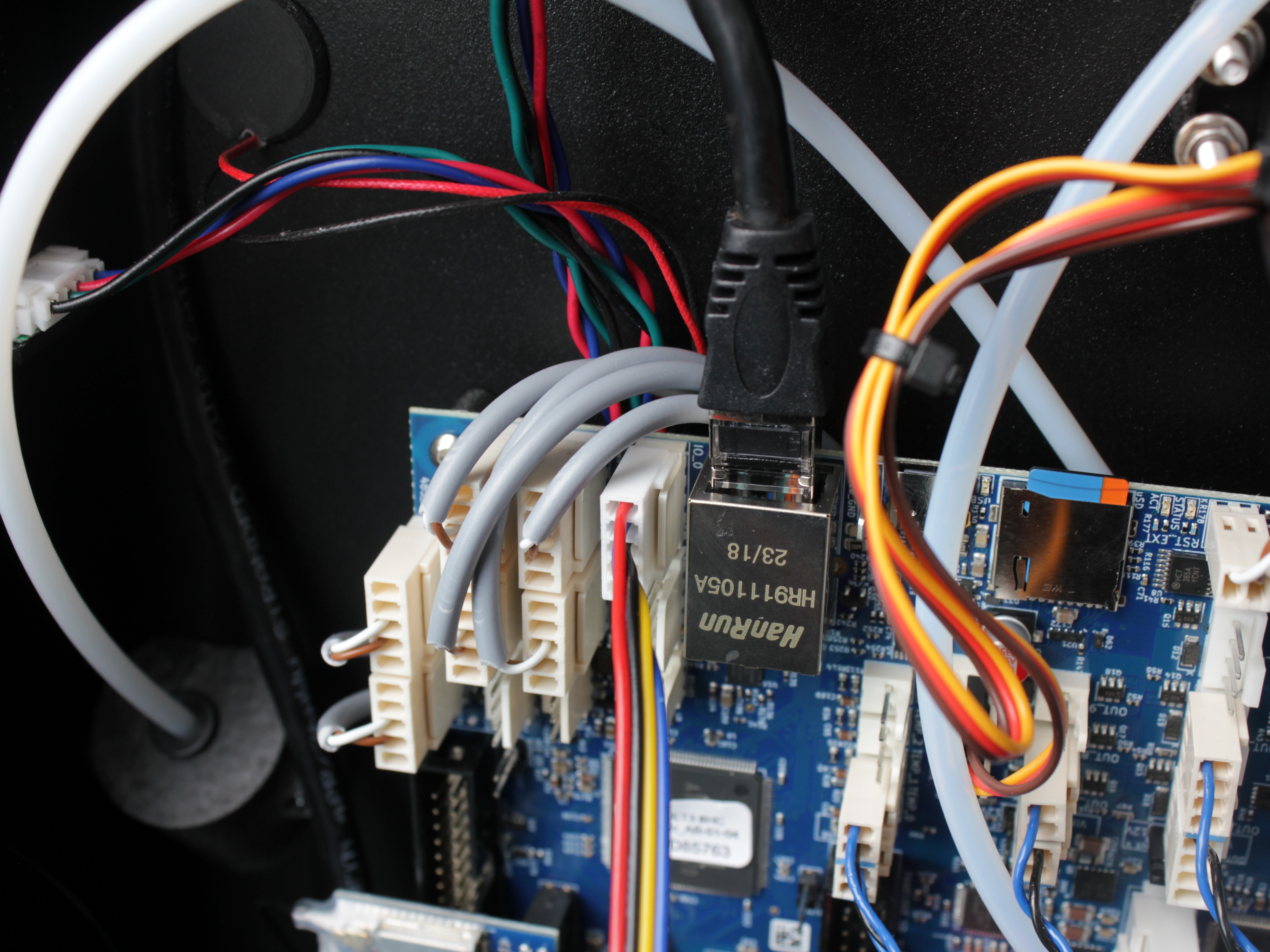
- Connect the touchscreen ribbon cable to the connector on the mainboard.
Connecting Power and First Boot
- Connect the included power cord to the printer and plug it into a grounded outlet rated for 20 amps.
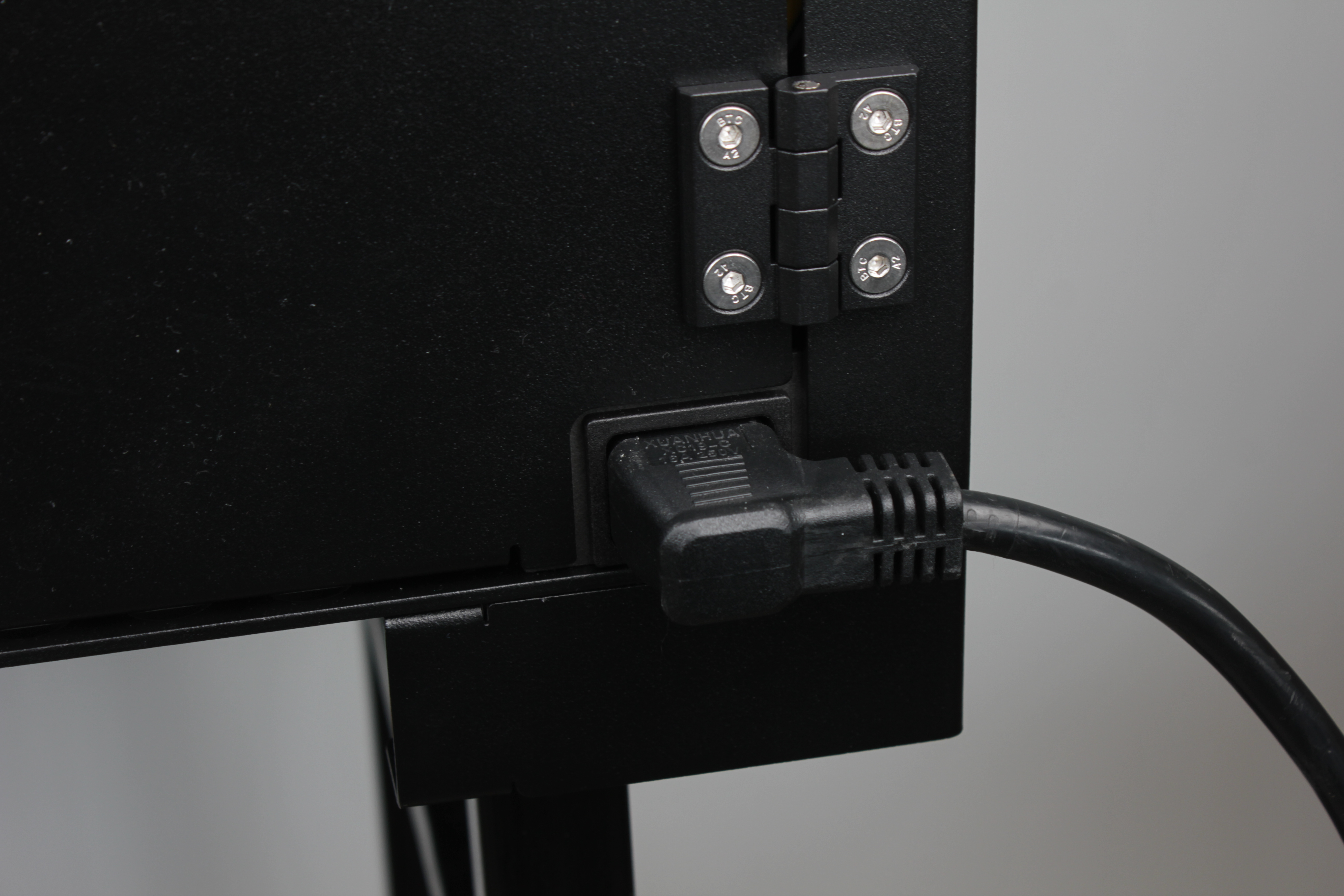
Proper grounding is crucial for safe operation
Proper grounding is crucial for safe operation. Never use an ungrounded outlet or adapter.
- Test the power button: turn the button clockwise to power on the machine. Press the button in to turn it off.
- Verify the touchscreen lights up and the Web Interface loads.
Safety Precautions
- Know the location of your facility's circuit breakers and how to turn them off in an emergency.
- Know the location of fire extinguishers and how to use them. Use only certified extinguishers rated for electrical fires.
- Know local procedures for first aid and emergency assistance.
- Use adequate lighting around the printer.
- Maintain recommended temperature and humidity in the operating area.
- Do not operate the printer in an environment with volatile or flammable compounds.
- Follow all local and national safety codes during setup and operation.
Support
If you could not find an answer here, reach out to our support team.