Endstop Issues
This guide covers diagnosis and resolution of endstop issues on the Vision Miner 22IDEX V4. Use it when an axis fails to home correctly or when the printer falsely reports filament runout. The 22IDEX V4 has 6 endstops and 2 filament sensors: 1× X-axis endstop, 1× U-axis endstop (second X-carriage, opposite side), 2× Y-axis endstops (one on each side), and 2× filament sensors (one per extruder – T0 and T1).
Before you begin - safety and risk
Read the Safety - Before You Begin article to understand the hazards involved in working on the Vision Miner 22IDEX V4 – including electrical, thermal, mechanical, and chemical risks. All procedures in this wiki are provided as recommendations only. By choosing to follow any procedure, you do so at your own risk.
For Z-probe issues (Z-axis homing and bed leveling), see the dedicated Z-Probe Troubleshooting Guide.
Endstop Locations
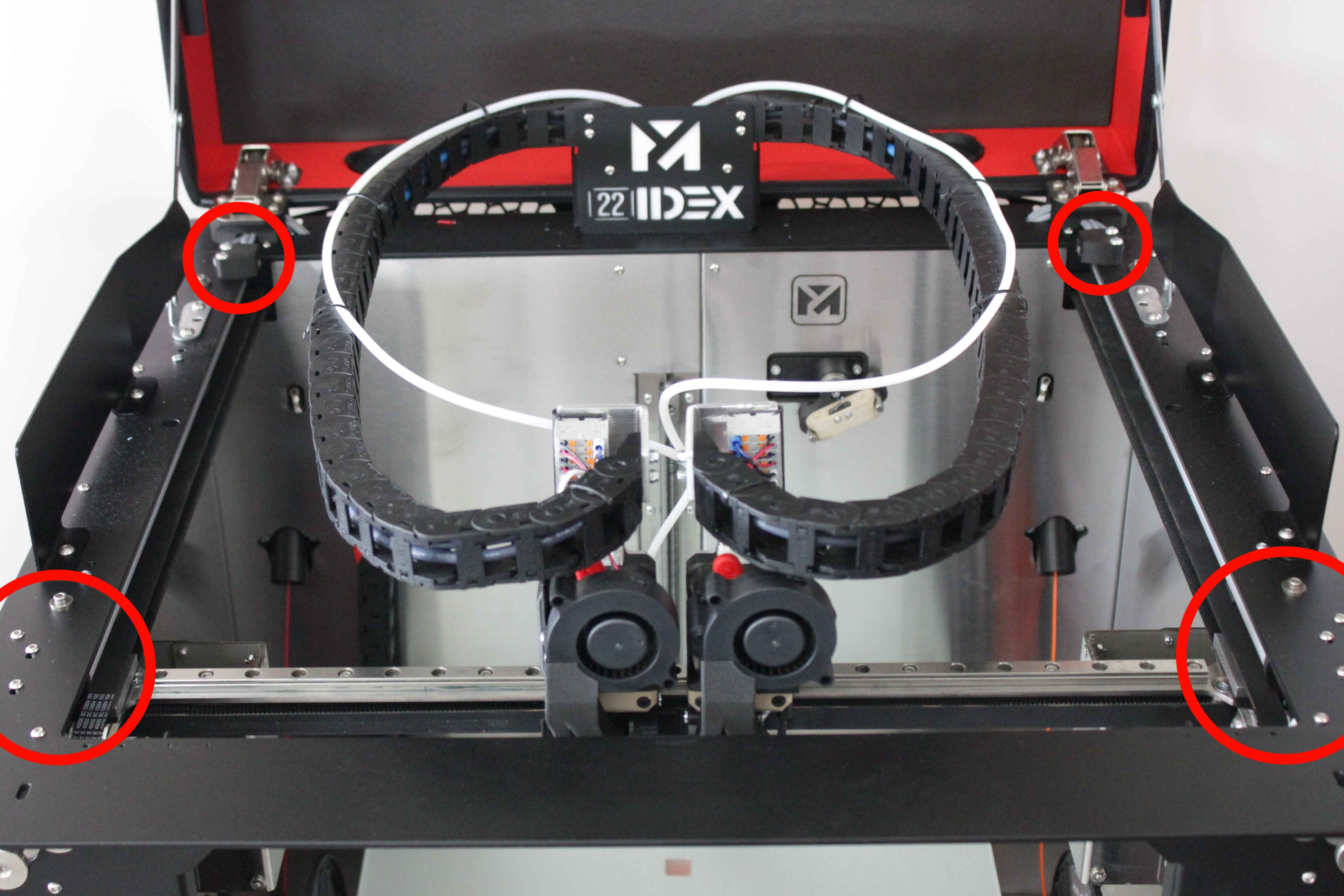
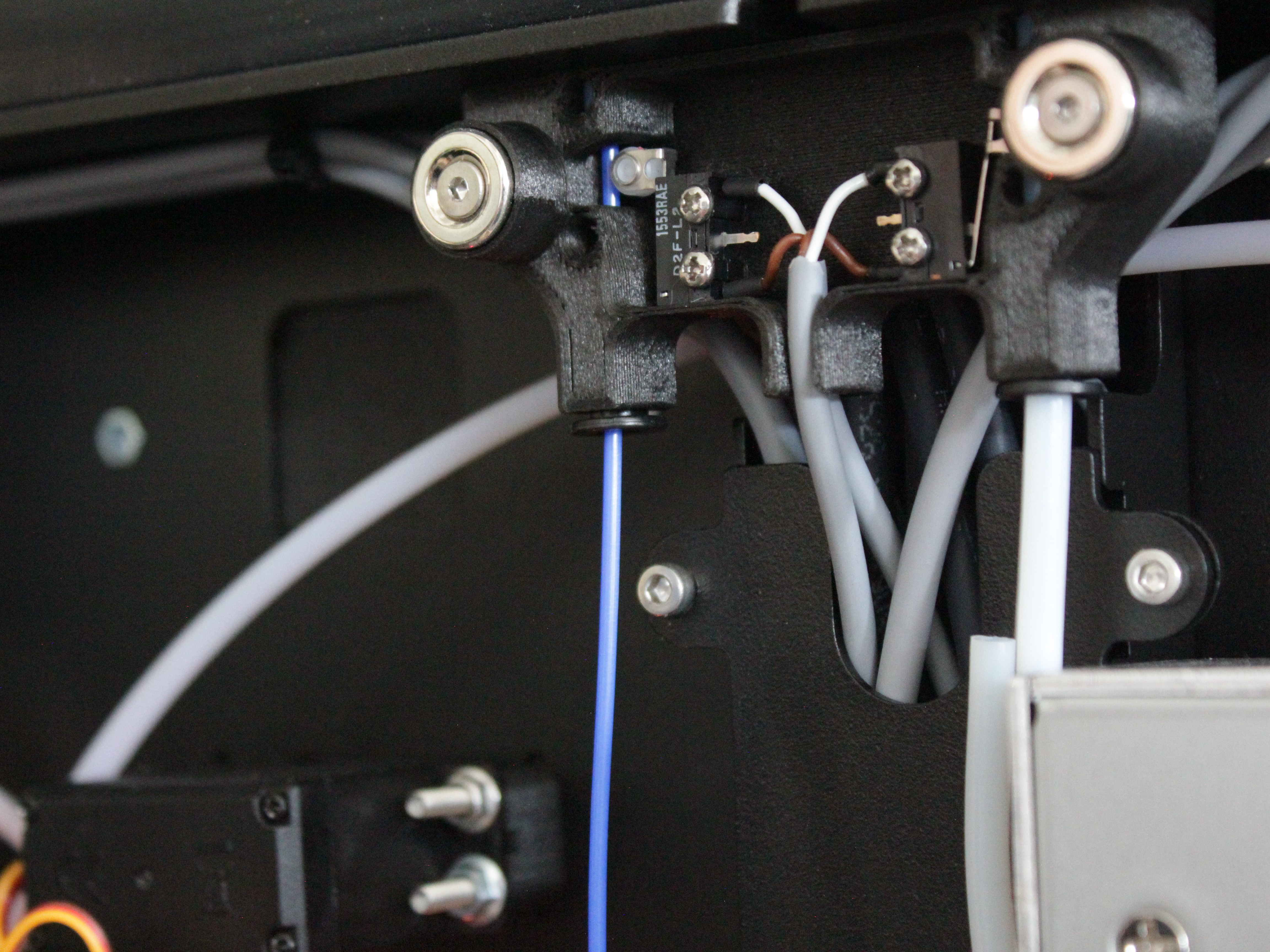
Before starting diagnostics, familiarize yourself with the endstop locations on the printer. The axis endstops are mounted on the gantry and control positioning of the X, U, and Y axes, while the filament sensors are located on the rear of the printer and monitor filament presence for each extruder.
Circles mark the location zones of all axis endstops. The Y-axis endstops are hidden behind the belts – they are located inside the circled zones.
Both filament sensors are located on the rear of the printer.
Running the Endstop Test
The printer has a built-in macro that tests all axis endstops and filament sensors in one sequence. Each endstop is tested individually – the macro asks you to press or trigger it 10 times, verifying repeatability and electrical response. This is the fastest way to identify a faulty endstop. The macro tests the Left Y and Right Y endstops separately. During normal operation they share one input, so this test is the easiest way to isolate which Y endstop has a problem.
-
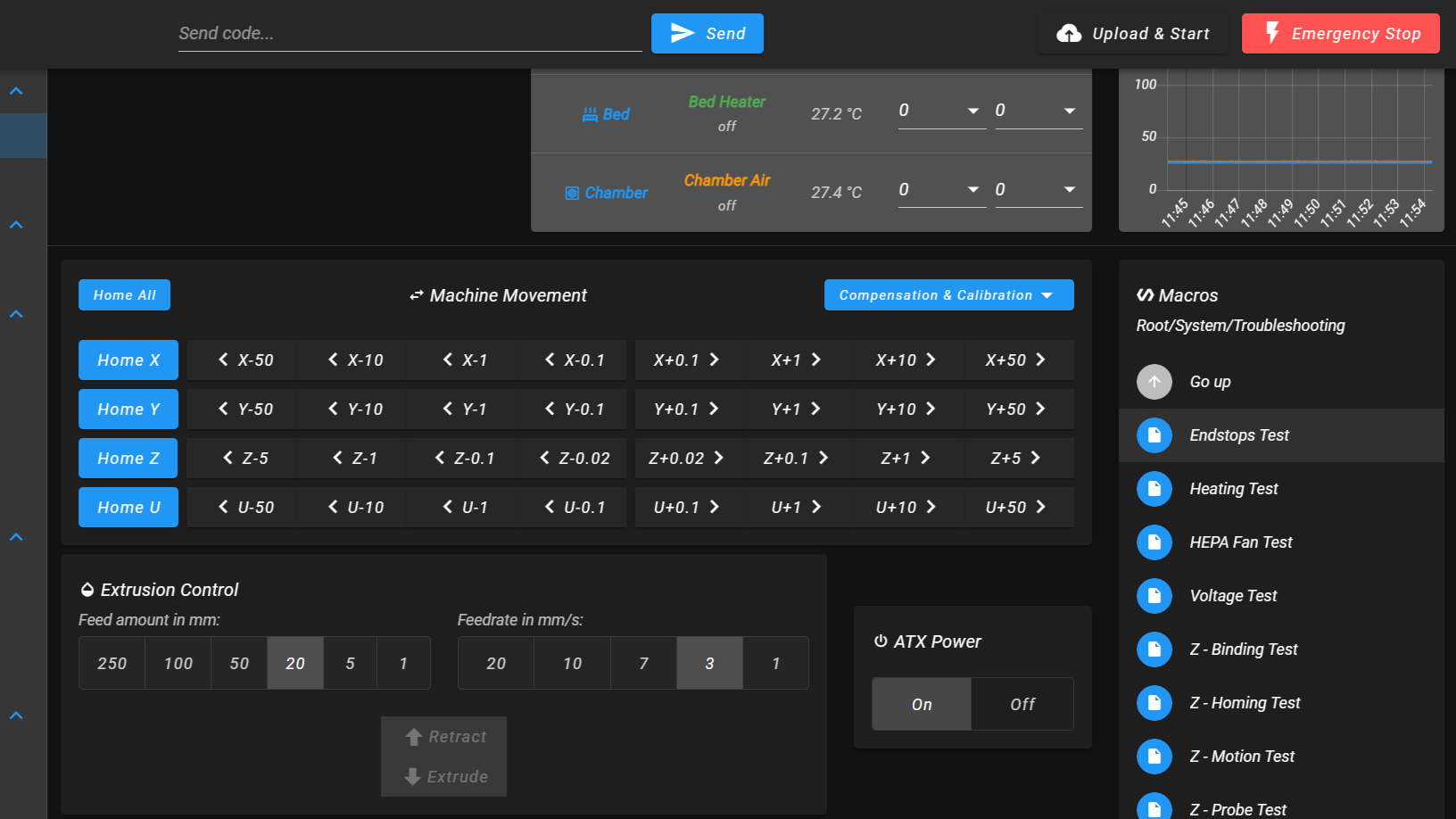
Open the Dashboard in the Web Interface.
-
In the Macros panel, navigate to System → Troubleshooting and click Endstops Test.
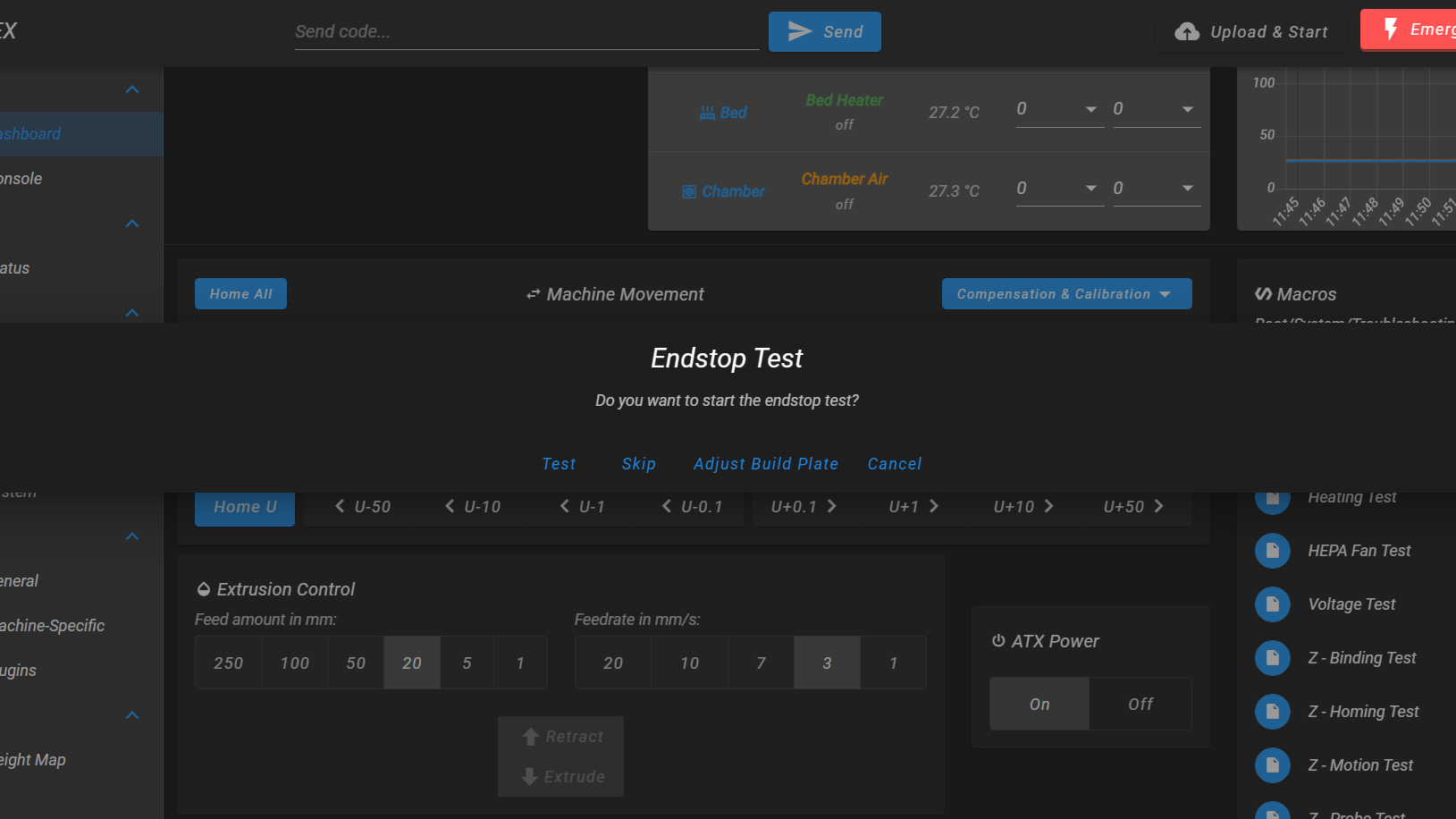
- A dialog appears with four buttons: Test, Skip, Adjust Build Plate, Cancel. Select Test to begin the full test sequence. Select Adjust Build Plate if the Y endstops are hard to reach – the printer will let you jog the bed to a comfortable position before testing.
Testing Axis Endstops
The macro tests axis endstops in this order: Left Y → Right Y → X → U. For each endstop, a prompt tells you which switch to press.
- Left Y-axis endstop. A message appears: "Please press the Left Y-axis endstop 10 times and wait for light signal." Press the Left Y endstop switch 10 times. The printer's LED changes color on each successful detection.
- Right Y-axis endstop. Same prompt for the right side. Press the Right Y endstop switch 10 times.
- X-axis endstop. Press the X endstop switch 10 times.
- U-axis endstop. Press the U endstop switch 10 times.
Testing Filament Sensors
After the axis endstops, the macro prompts for filament sensor tests. Each sensor test has its own dialog with Test, Next (skip this sensor), or Cancel.
- Left filament sensor (T0). Select Test. Insert and remove a piece of filament through the left sensor 10 times. The LED changes on each successful detection.
- Right filament sensor (T1). Select Test. Insert and remove filament through the right sensor 10 times.
Interpreting Test Results
- All tests pass – the printer confirms success with an LED signal after each completed test. If all 6 tests finish without error, all endstops and filament sensors are working electrically.
If a test fails, one of these error messages appears:
- "Error: [endstop name] is already triggered" – the endstop is stuck in the triggered state before the test begins. Check for a physical obstruction holding the switch, or a wiring short.
- "Time for press the [endstop name] has expired" – the macro did not detect 10 presses within 120 seconds. The endstop is likely not responding or responding inconsistently.
Note which specific endstop failed – the error message names it. This tells you exactly where to focus your troubleshooting.
Next steps based on test results:
- If an axis endstop or filament sensor test failed → see If an Endstop Test Fails below.
- If all axis endstops passed but homing still fails → see Endstop Passes Test but Homing Still Fails below.
- If filament sensors pass the test but trigger incorrectly during printing → see Filament Sensor Triggers Incorrectly During Printing below.
If an Endstop Test Fails
This section applies when the test macro reports an error for an axis endstop (X, U, or Y) or for a filament sensor. The inspection procedure is identical for both types: check the switch itself, its wiring, and its connector on the mainboard.
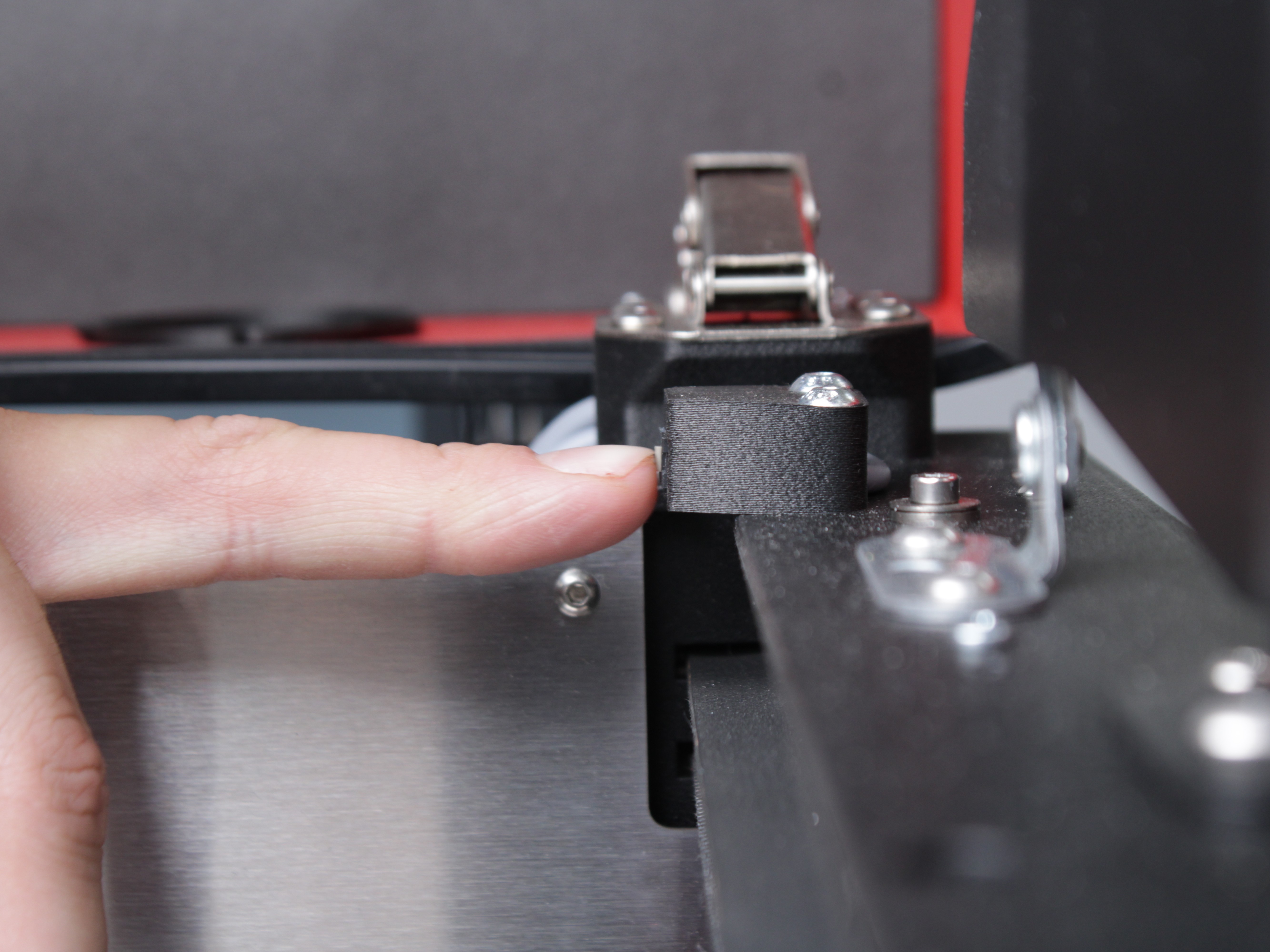
- Inspect the endstop switch itself. Press the faulty endstop by hand. You should hear and feel a crisp, distinct click – both on press and release. Compare it to another endstop on the machine that passed the test. If the click is mushy, silent, or the switch feels stuck, the endstop is mechanically faulty and needs replacement.
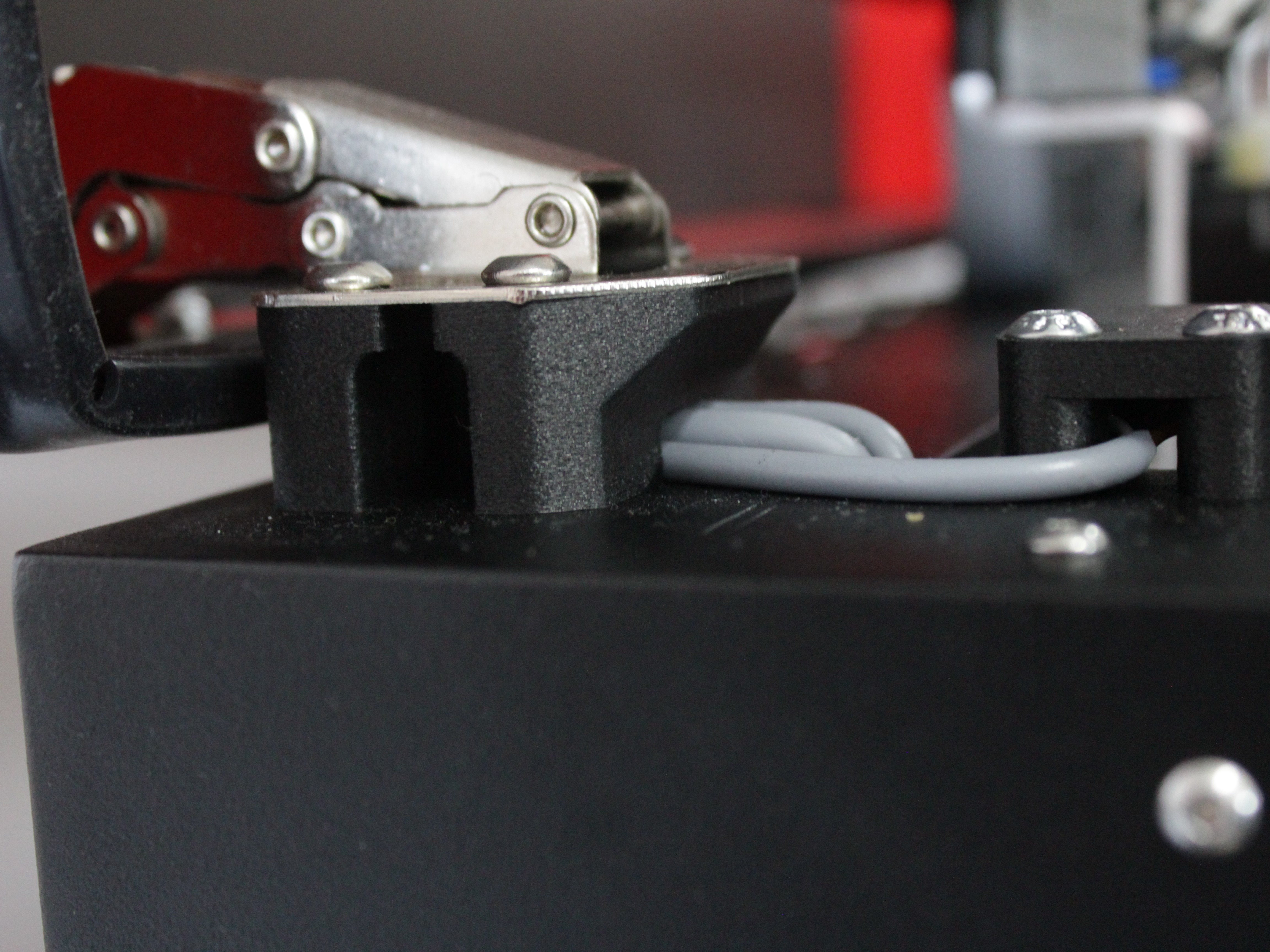
- Inspect the wire path at the lid hinge spacers. The endstop wires run underneath the lid hinge spacers – the spacers sit between the lid hinge and the frame, and there is a cavity inside each spacer for the wires. It is possible for the wire to get pinched when the lid is installed at the factory. Inspect the wire where it passes through each spacer and check for crushed or damaged insulation.
- Inspect the mainboard connector. Turn off the printer and unplug it from the power outlet before inspecting any connectors or wiring on the mainboard. Wait at least 60 seconds for the capacitors to discharge. Locate the connector of the faulty endstop on the mainboard and unplug it.
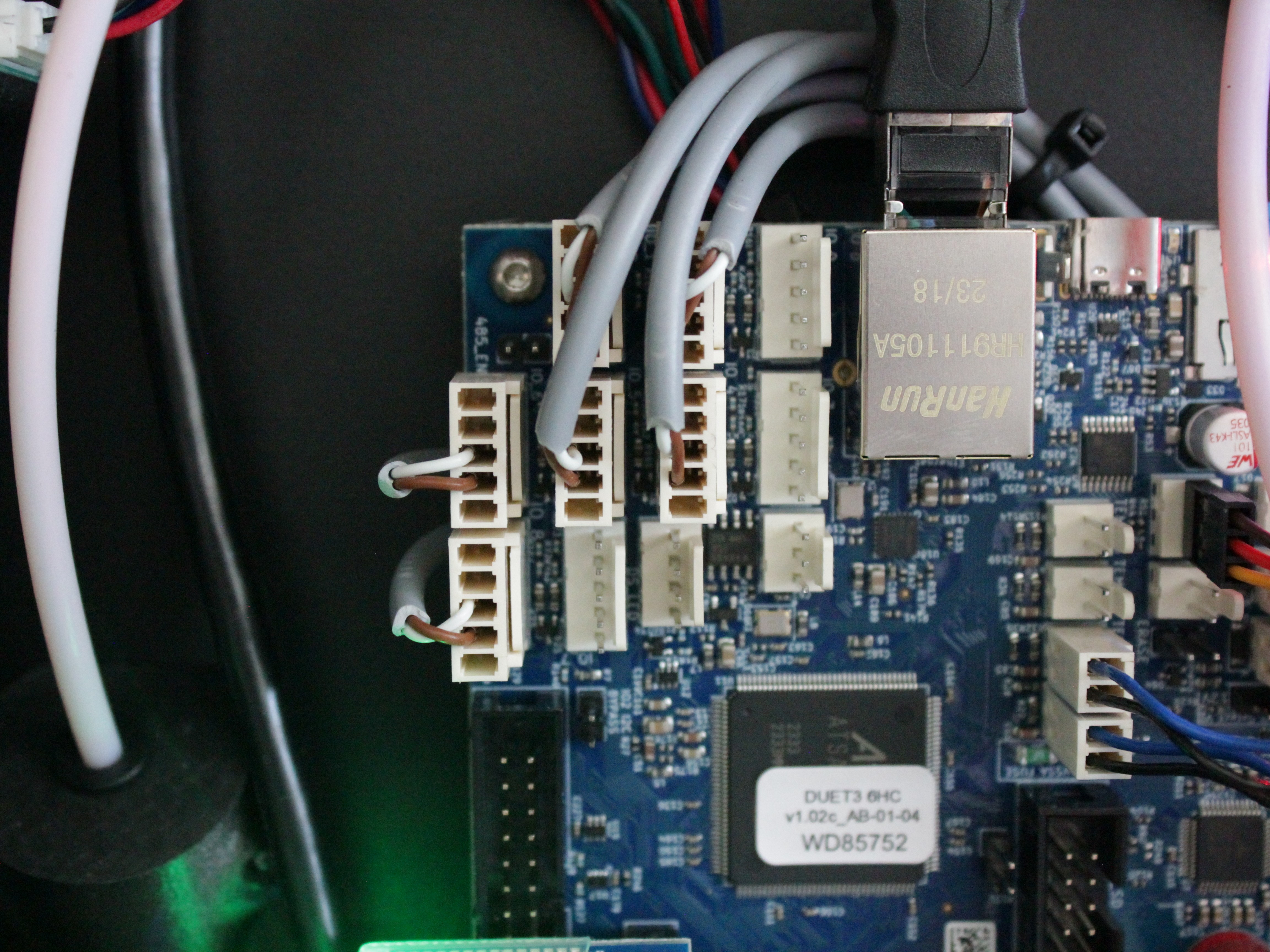
Here is a wiring diagram for reference:
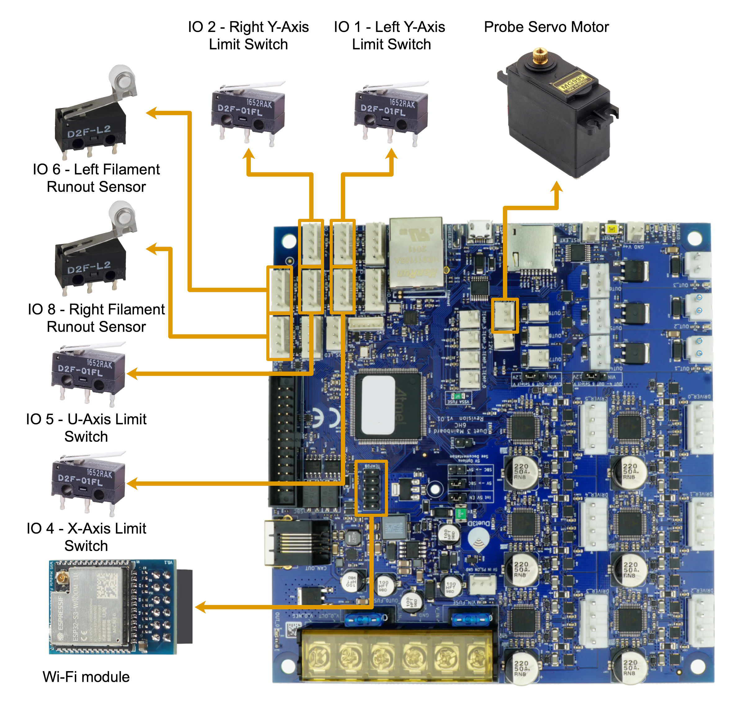
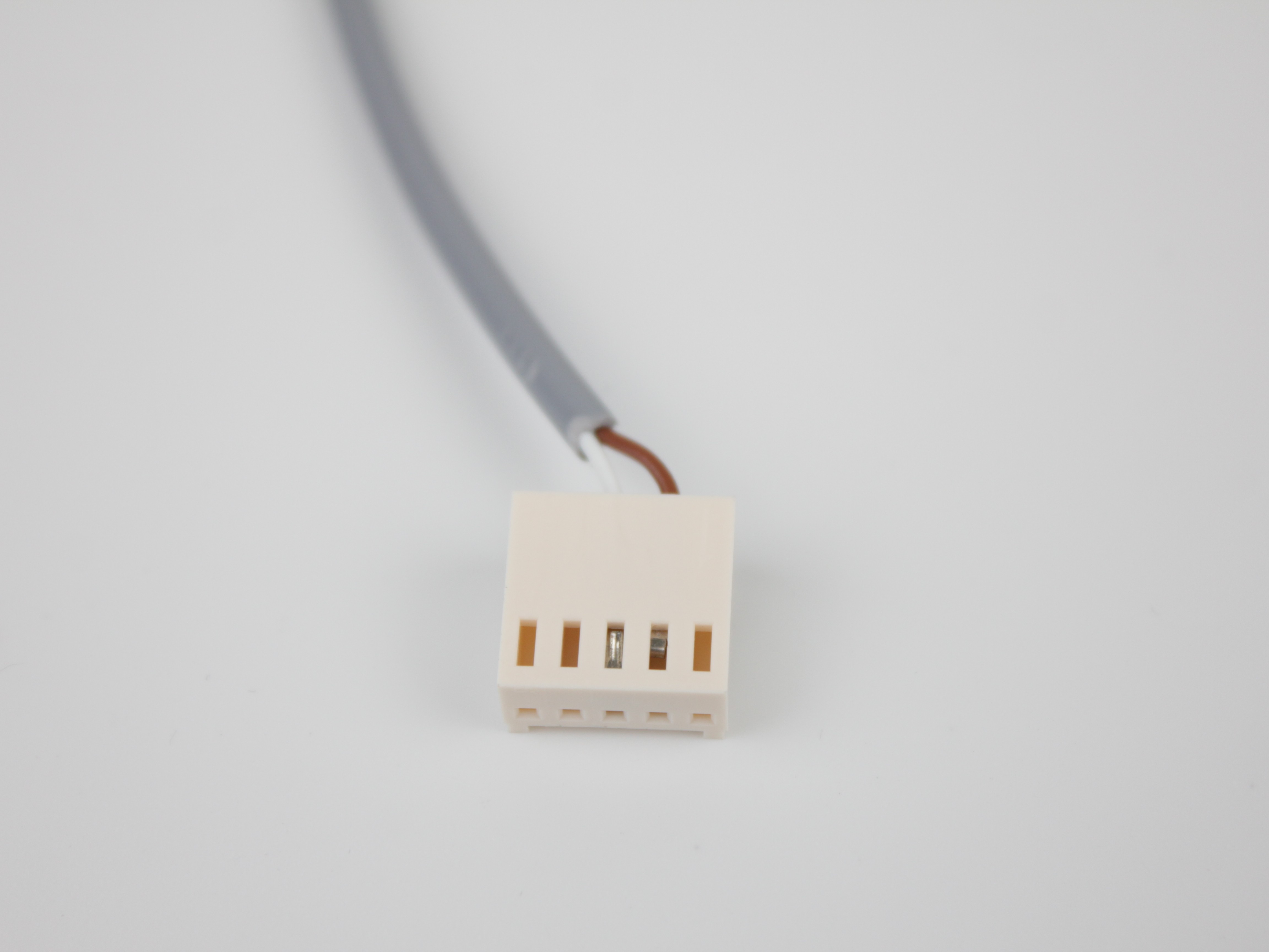
- Inspect the metal pins inside the connector and the socket on the mainboard. Look for:
- Pins pulled out of the connector housing
- Bent or broken pins
- Oxidation or corrosion
- If the pins look clean and undamaged, re-seat the connector firmly. Power on and re-run the test macro (steps 1–3). If the endstop still fails after all checks, contact Vision Miner support with a description of which endstop failed and what you found during inspection.
Endstop Passes Test but Homing Still Fails
This section applies when the endstop passes the test macro but the physical homing procedure still fails.
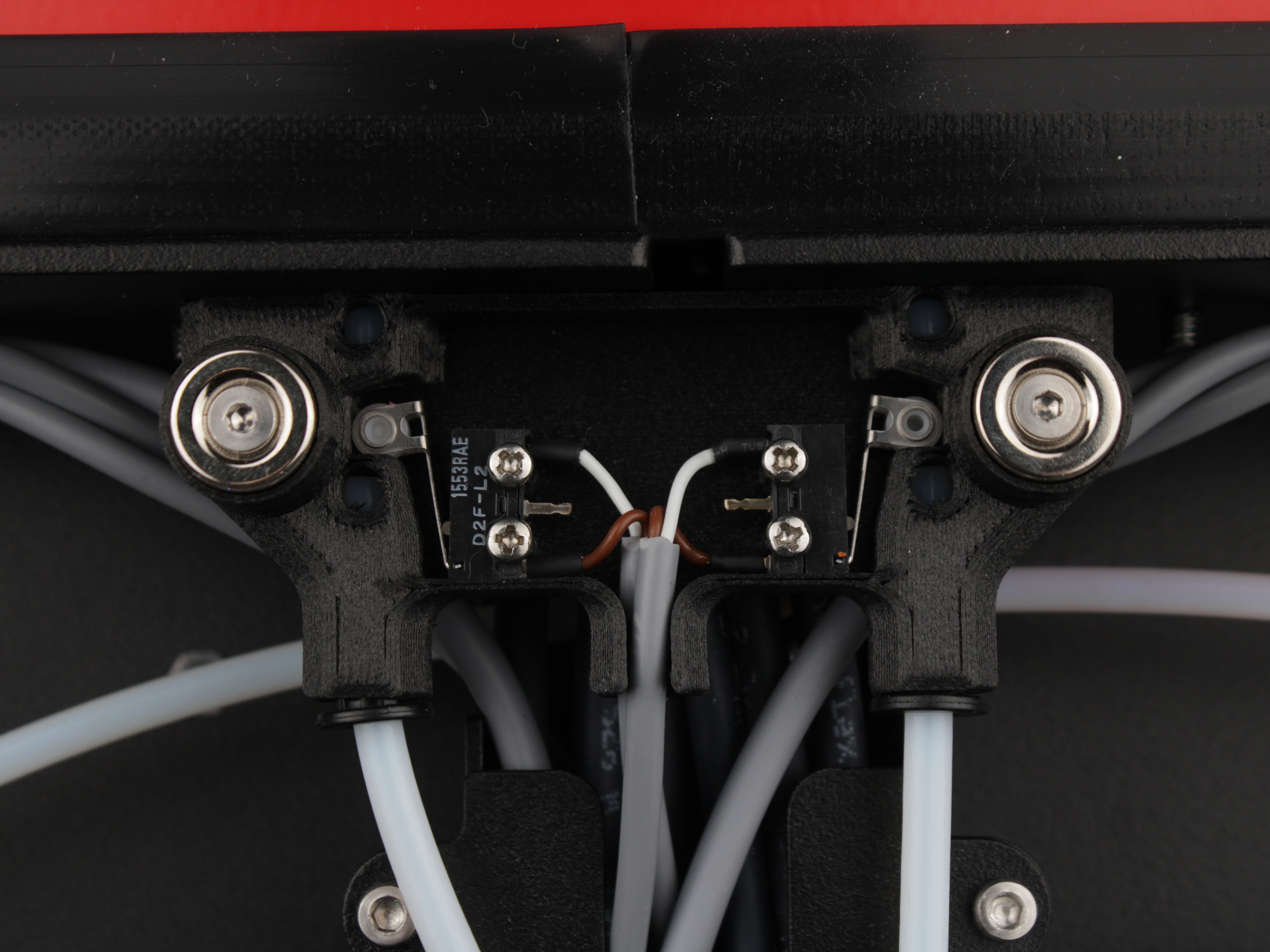
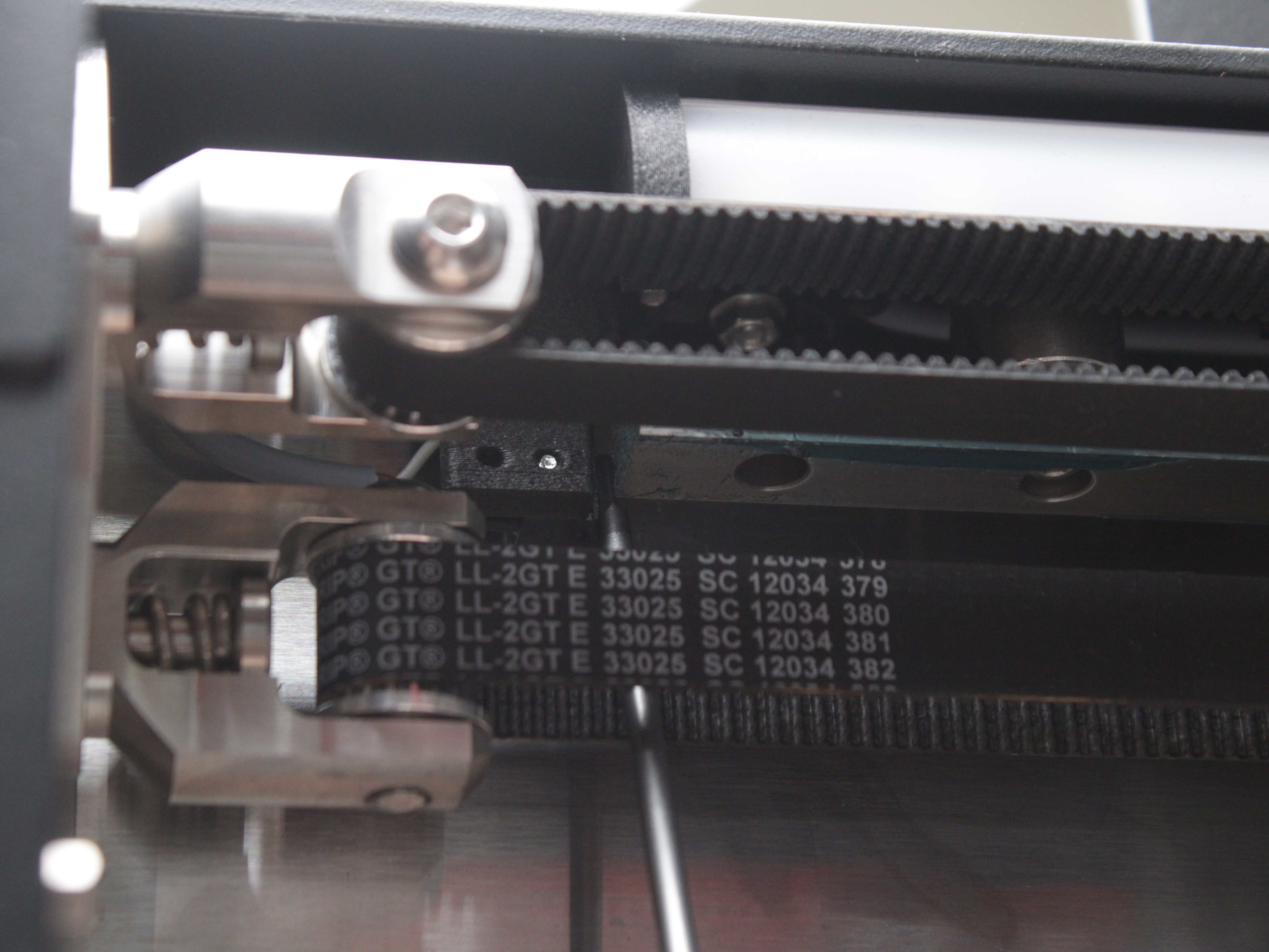
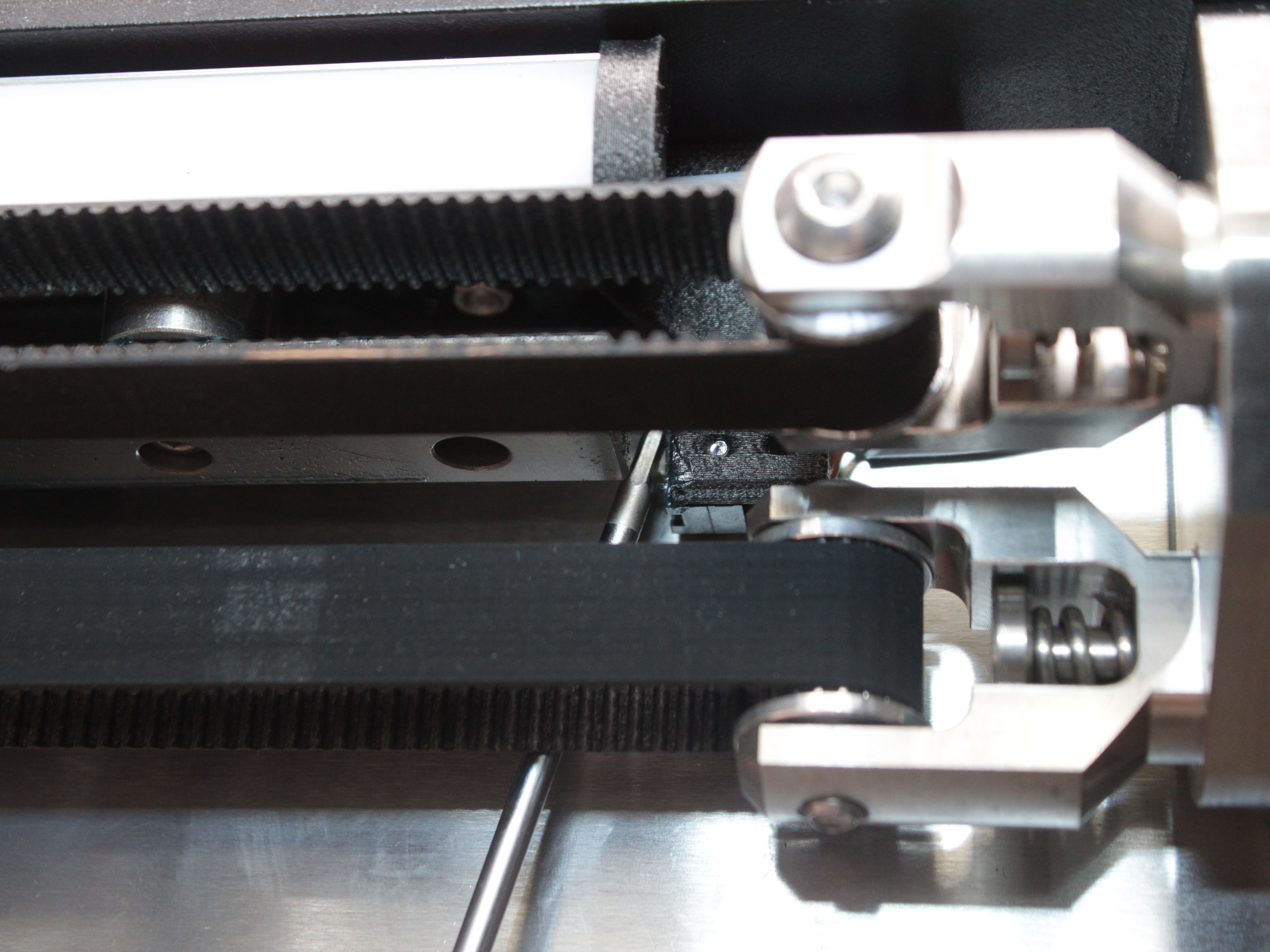
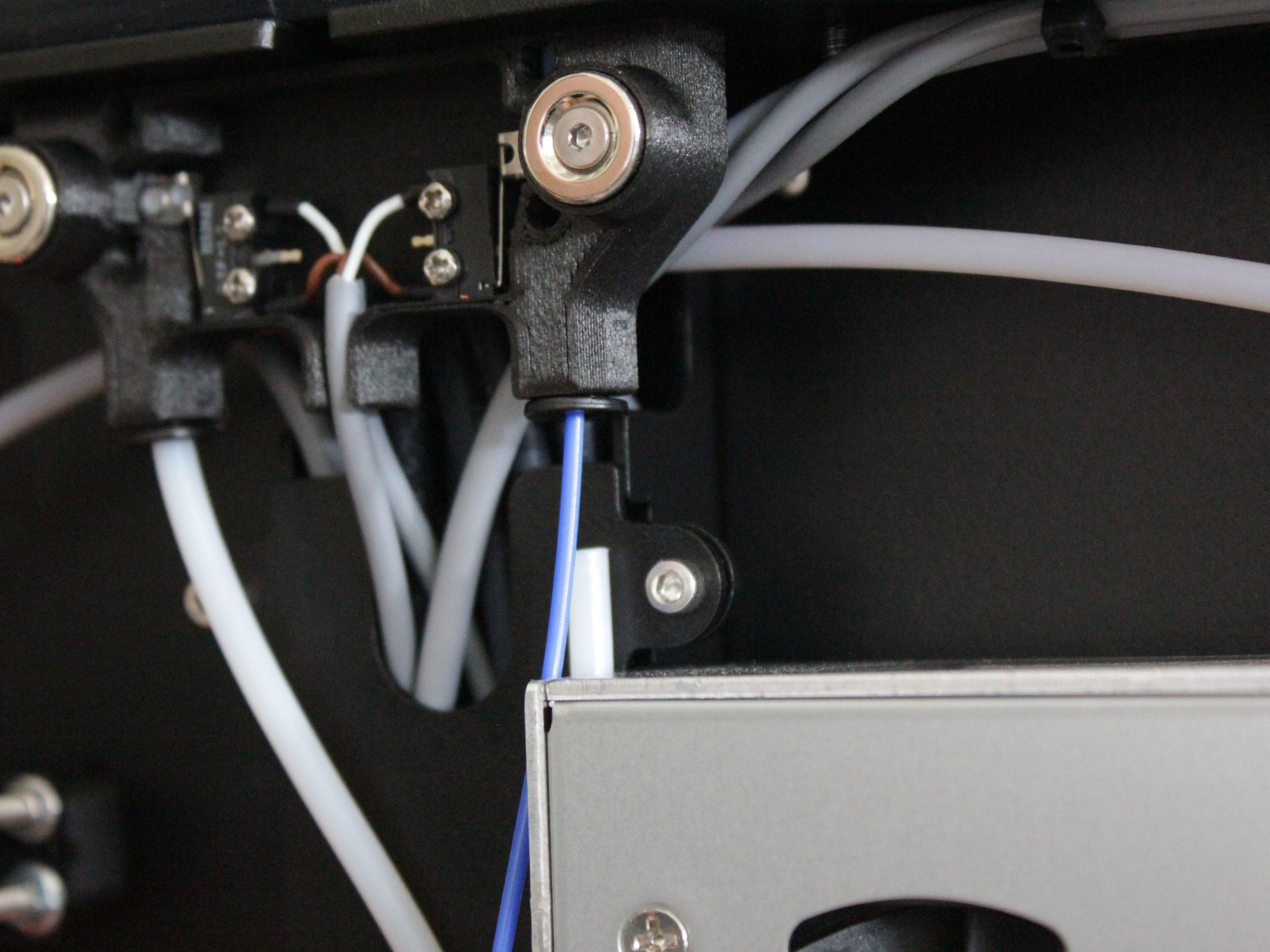
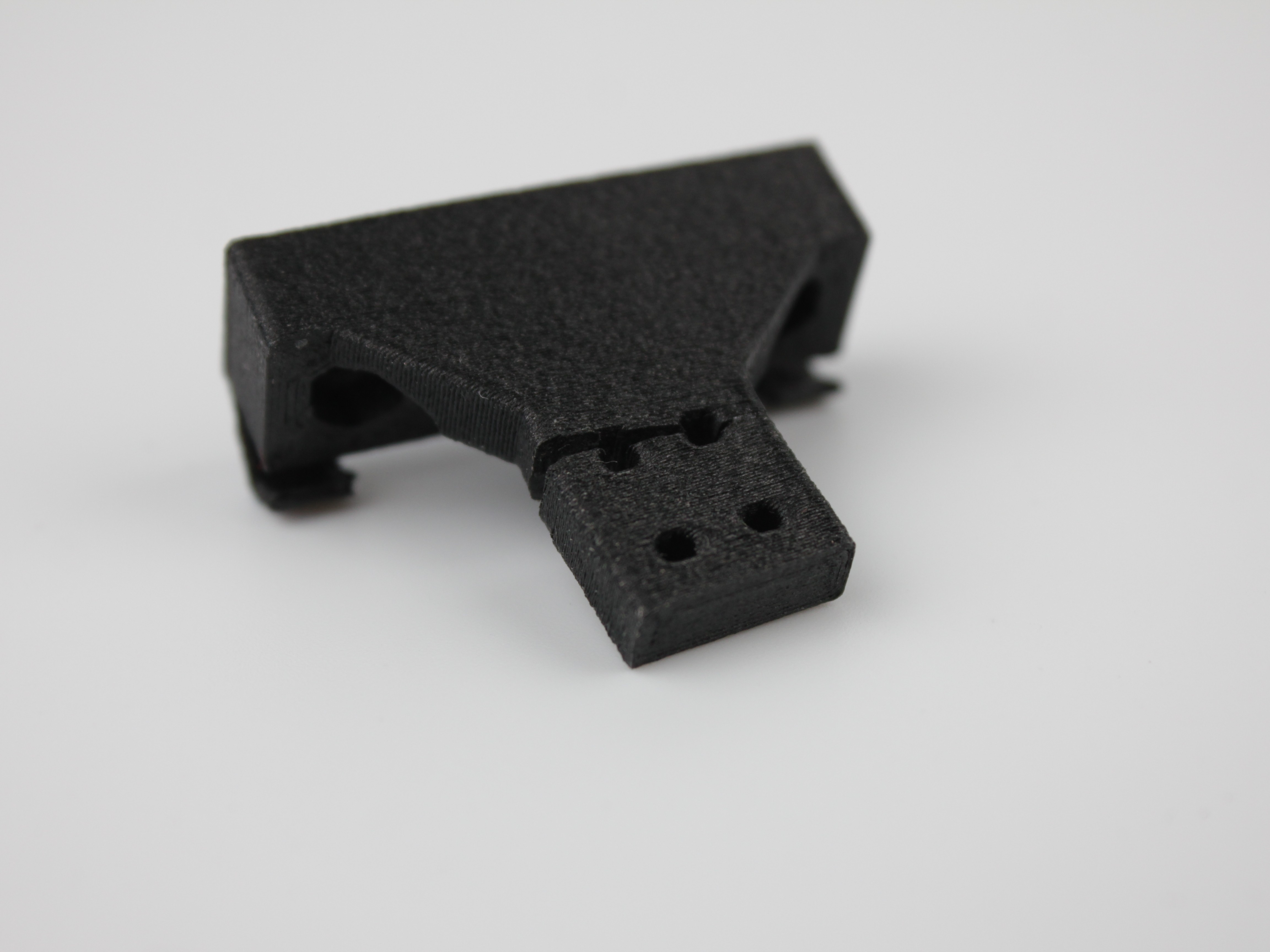
- Inspect the 3D-printed Y-axis endstop holder. The Left Y and Right Y endstops are mounted on 3D-printed holders. Inspect the holder body carefully – look for cracks, warping, or breakage. A damaged holder can shift the endstop position so the switch no longer triggers reliably during homing.
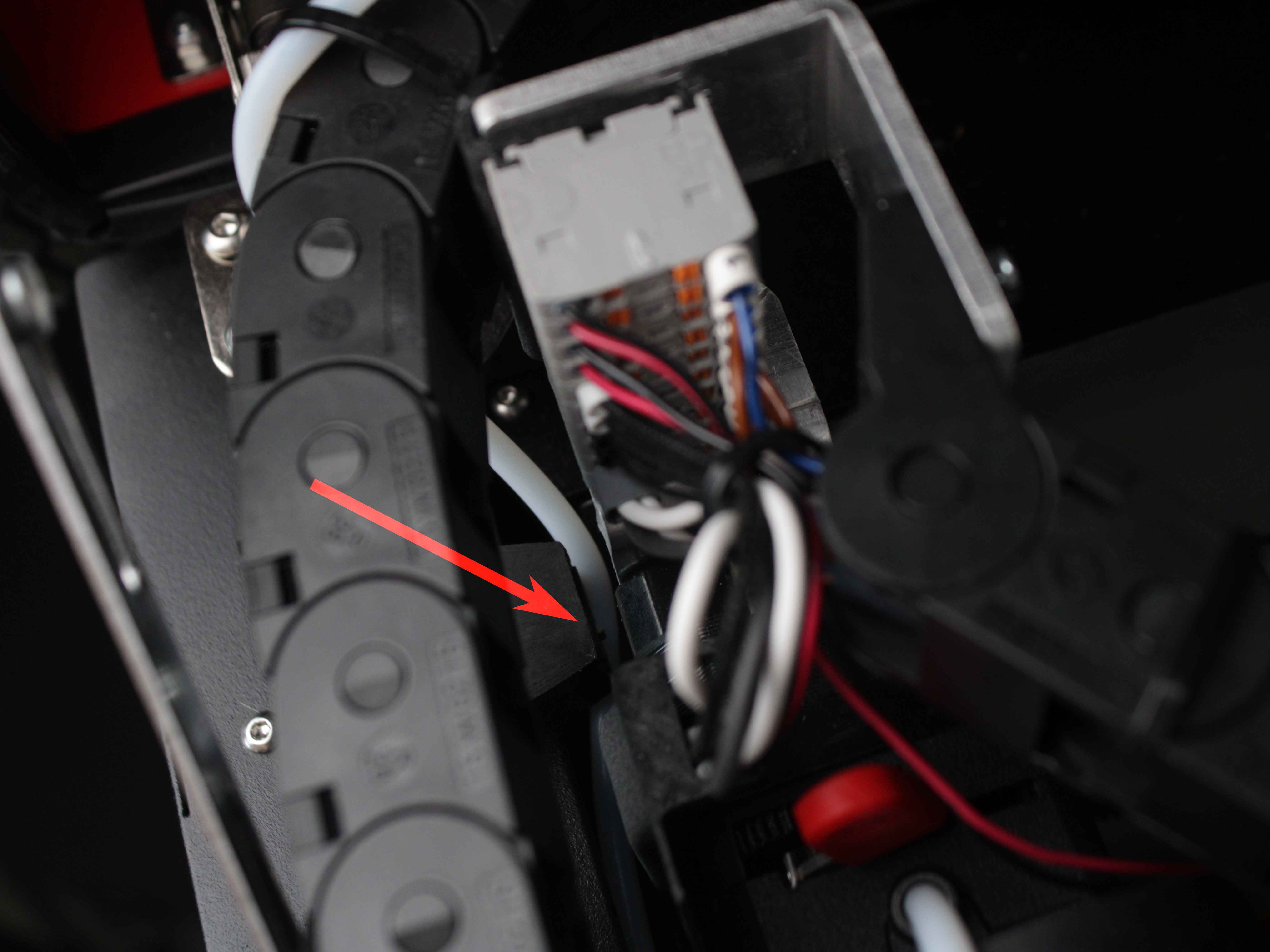
- Verify motor body overlap with the endstop (X/U axes). During X and U homing, the extruder motor body on each toolhead is the part that physically presses the endstop switch. Manually slide the toolhead toward the endstop and confirm that the motor body fully reaches and presses the switch lever. If the toolhead does not reach the endstop, check that nothing is obstructing its movement: the filament tube can get caught between the endstop and the motor, or dirt or foreign debris can block the head's travel to the endstop.
-
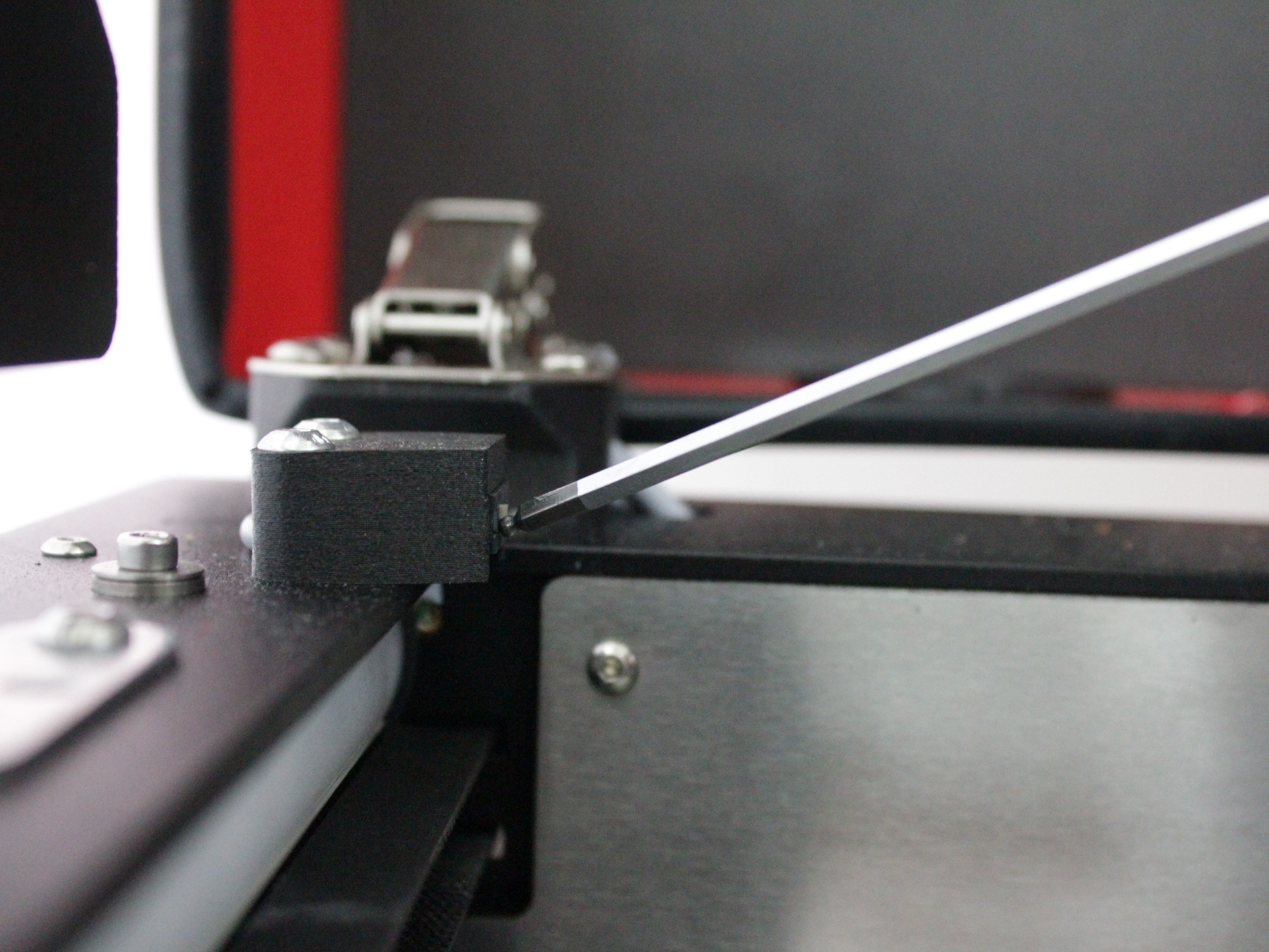
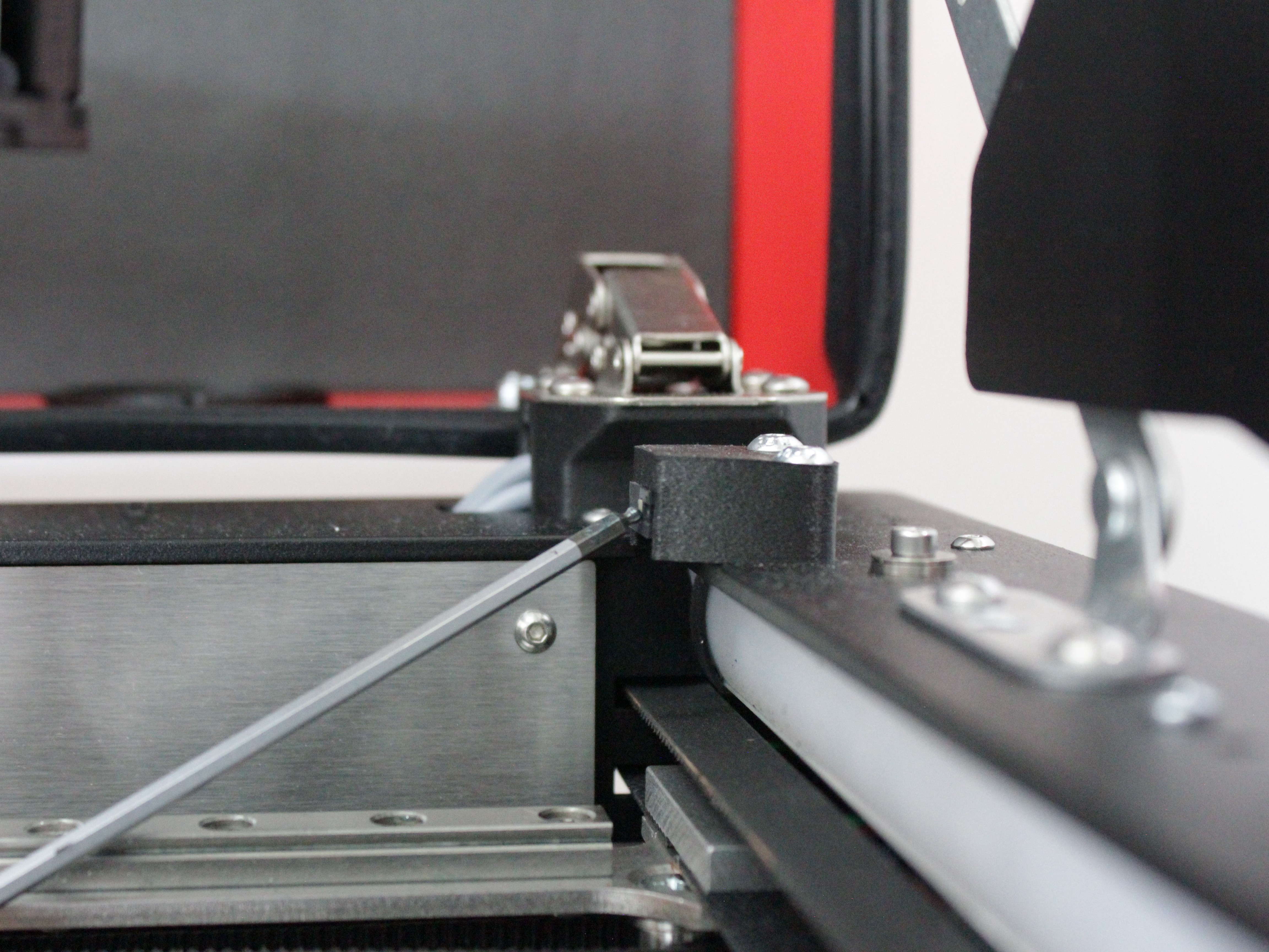
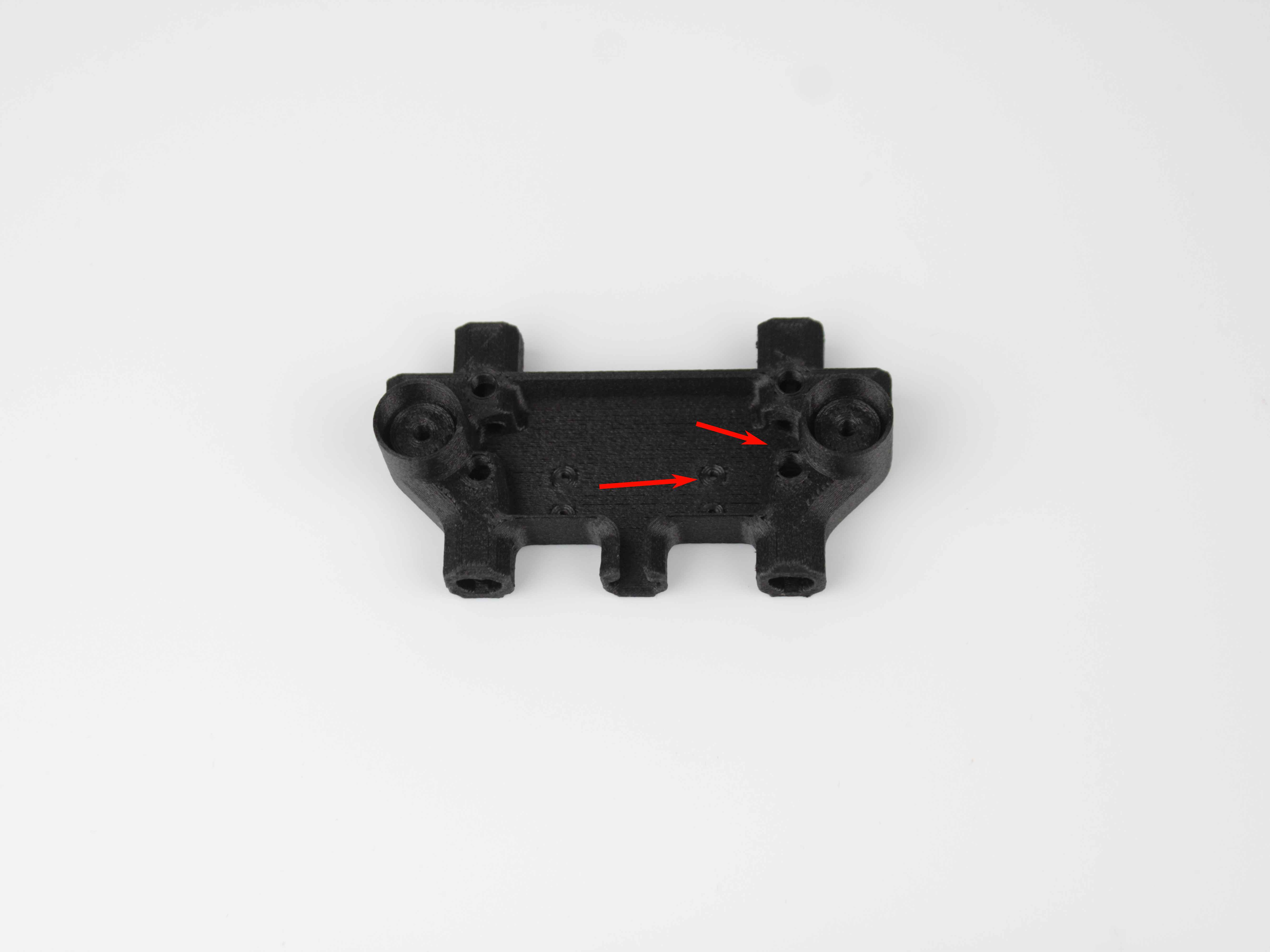
Inspect the 3D-printed endstop mounting bracket. Check for:
- Cracks or deformation
- Loose attachment to the housing
- Misalignment causing inconsistent or incorrect triggering
-
If a mounting bracket is cracked or broken, replace it with a correctly printed part. Contact Vision Miner support if you need the STL file or a replacement.
Z-Probe Issues
Symptoms that bring you here: During Z-homing or calibration, the nozzle crashes into the bed, or the printer reports probe-related errors.
The Z-probe is not covered by the Endstops Test macro. It has its own dedicated troubleshooting guide with a built-in self-test macro and step-by-step diagnosis – see the Z-Probe Troubleshooting Guide.
Filament Sensor Triggers Incorrectly During Printing
If the filament sensor passes the test macro but triggers false alerts during active printing, the issue is likely mechanical – not electrical. There are two factors to check: the condition of the sensor housing and the condition of the switch itself.
- Inspect the sensor housing. Minor dimensional inaccuracies or wear in the 3D-printed housing can increase the internal clearances. Pay particular attention to the area where the ball roller of the switch makes contact – this part wears down over time, and once it is worn enough, the endstop triggers poorly or only intermittently. As a result, the filament presses the switch lever poorly and does not push it all the way, causing the sensor to trigger falsely during printing. If the housing is damaged or has enlarged clearances, replace it. You can reprint the housing yourself, or Vision Miner can send a replacement housing.
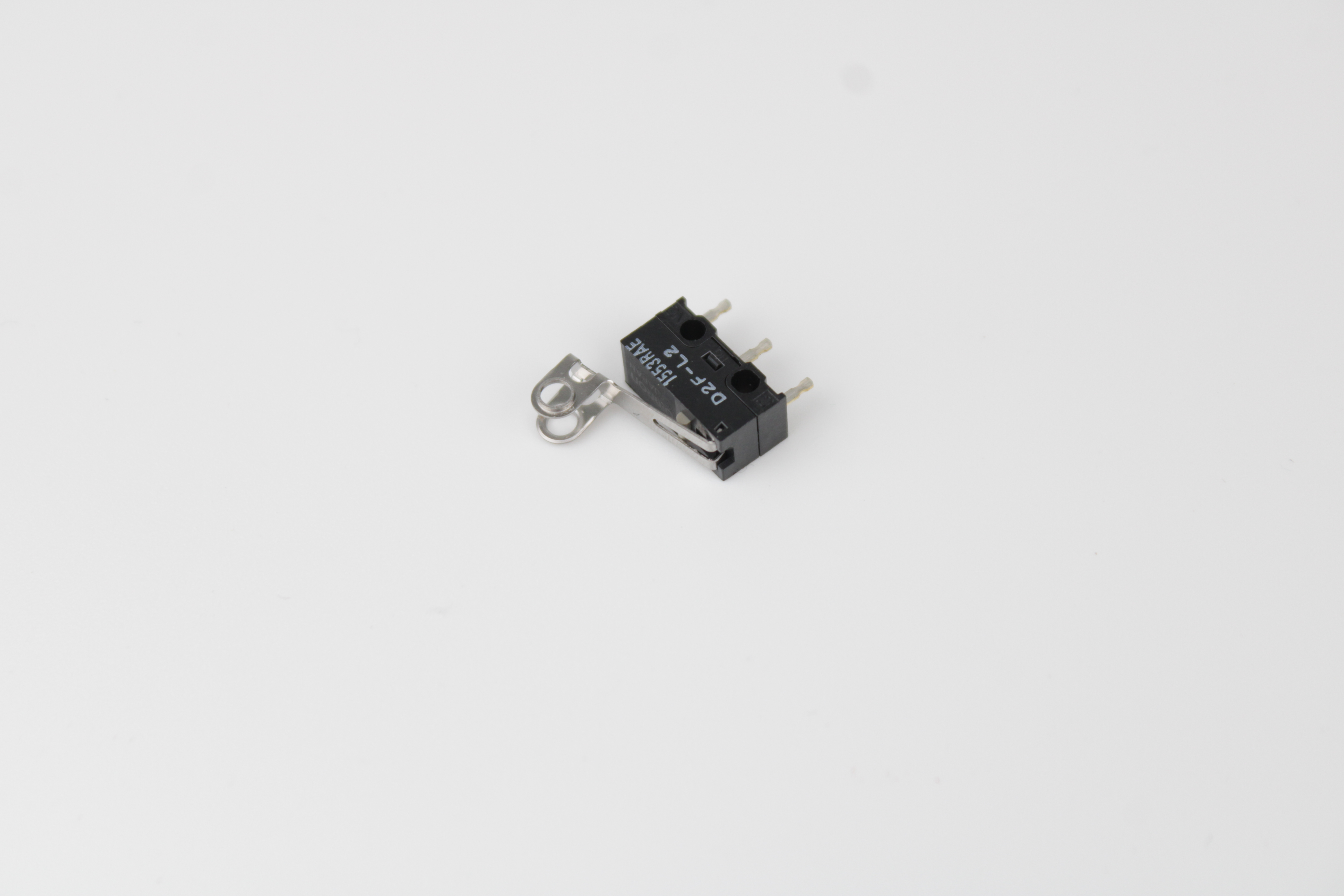
- Inspect the sensor switch itself. The filament sensor switch has a roller that the filament constantly presses against with a certain force. Over time, the roller can wear out, become damaged, or fall out entirely – once the roller is missing, the switch can no longer trigger correctly. If the housing is fine but the roller or switch itself is damaged, replace the sensor switch. Contact Vision Miner support to order a new filament sensor switch.
FAQ
Support
If you could not find an answer here, reach out to our support team.