Z-Probe Issues
This guide helps you diagnose and fix Z-Probe problems on the Vision Miner 22IDEX V4. Z-Probe issues fall into two categories:
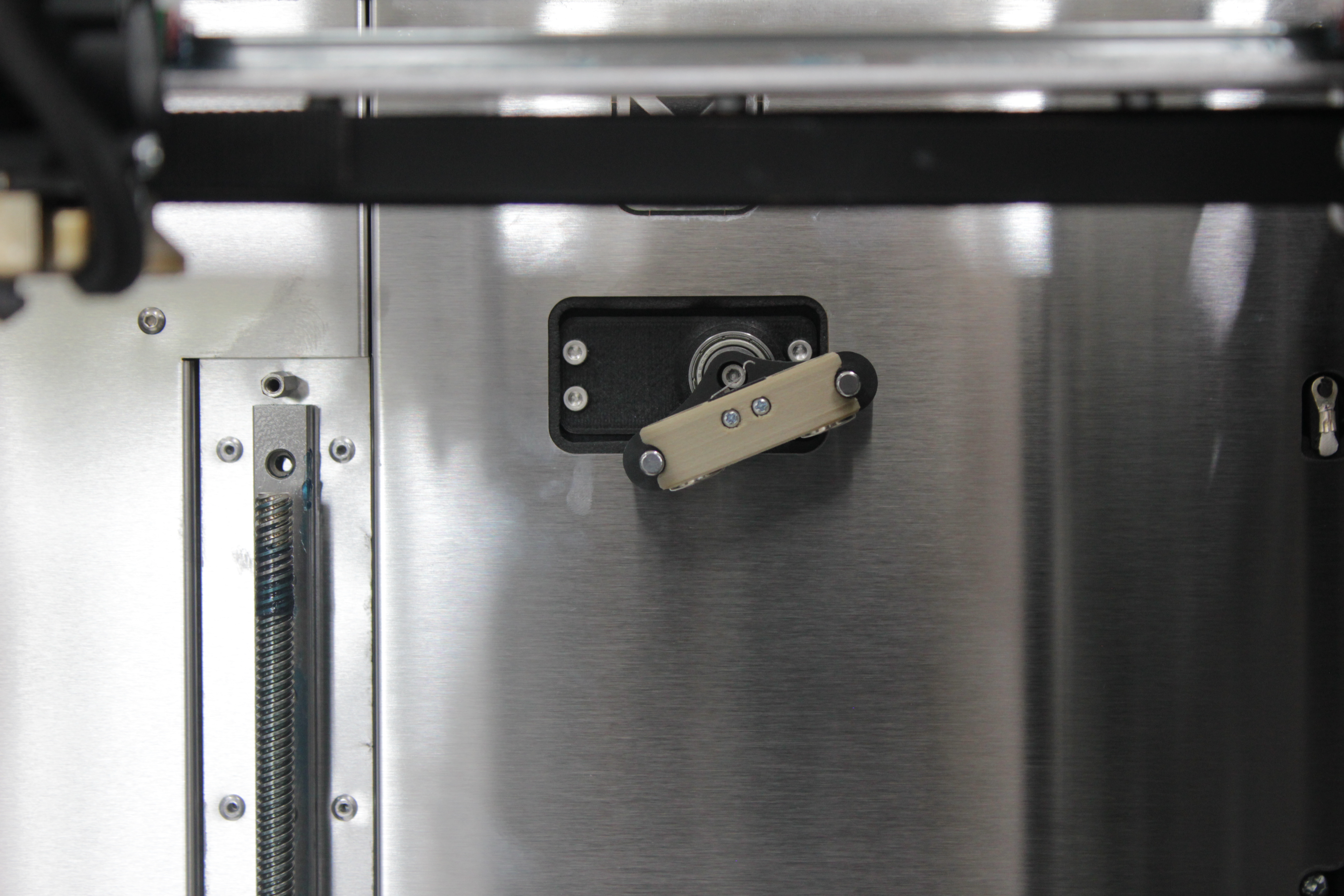
- Mechanical – the probe does not physically reach the dock station at the back of the machine, or the servo angle is wrong. This is solved by running the Probe Calibration macro, which adjusts the X pickup position and the servo angle. See the Z-Probe Calibration Guide for the full procedure.
- Electrical – the probe circuit has a short or open circuit, and the printer cannot detect the probe correctly. This guide walks you through the built-in self-test and manual troubleshooting for electrical issues.
For V3 users
This guide is for the V4 printer, which has an automated self-test and servo-based pickup system. If you have a V3 printer, see the V3 Z-Probe Issues Guide instead – the electrical troubleshooting principles are the same, but V3 uses LED indicators and manual diagnosis.
Before you begin – safety and risk
Read the Safety – Before You Begin article to understand the hazards involved in working on the Vision Miner 22IDEX V4 – including electrical, thermal, mechanical, and chemical risks. All procedures in this wiki are provided as recommendations only. By choosing to follow any procedure, you do so at your own risk.
Start here: if you are not sure whether your problem is mechanical or electrical, run the Z - Probe Test macro first (see Running the Z-Probe Self-Test below). It will tell you exactly what is wrong.
On this page
Work top to bottom, or jump straight to your problem:
- How the Z-Probe works – the magnets, dock, and circuit, in brief.
- Run the Z-Probe Self-Test – start here if you do not know what is wrong; it pinpoints the failing part in a few minutes.
- Troubleshooting by symptom – jump straight in if you already recognize the error code or symptom (table below).
- Probe State Reference – LED indicators and Web Interface values, kept at the bottom for when a step needs the detail.
Jump by error code or symptom
These are the errors the printer reports while picking up or placing the probe during homing. Each is written to the event log (Web Interface > Console), and most also pop a dialog. The attachedcheck/detachedcheck safety routines catch them before any probing move, so the operation stops safely – the nozzle does not crash.
Most faults are one of two electrical states:
- Scenario A – short / closed circuit: value stuck at 0; the circuit reads "attached" with no probe present (usually conductive filament residue or a pinched signal lug).
- Scenario B – open circuit: value stays at 1000; the probe is never detected.
If the circuit is healthy (the self-test passes) but pickup or placement still fails, the cause is mechanical misalignment → 2. Pickup & Placement.
| Event-log message (and dialog) | When it happens | Go to |
|---|---|---|
| "Z probe was not picked up" — dialog "Probe Pickup Failed" | Picking the probe up | Self-test fails → Scenario B – 5; self-test passes → 2. Pickup & Placement |
| "Probe not connected after pickup attempt" — dialog "Z-Probe Not Connected" | Picking up during homing | Scenario B – 5. Probe Not Detected |
| "Z-probe short circuit detected" — dialog "Z-Probe Short Circuit" (Run Z-Probe Test / Conductive Filament / Dismiss) | Short-circuit check before pickup | Scenario A – 3. Short Circuit |
| "Probe removal failed" — dialog "Probe Removal Failed" | Placing the probe | 2. Pickup & Placement; if value stays 0 → Scenario A – 3 |
| "Probe still connected after placement attempt" — dialog "Probe Still Attached" | Placing during homing | 2. Pickup & Placement; if value stays 0 → Scenario A – 3 |
| "Probe not detected at start of placing" — warning, no dialog | Start of placing | Probe was lost or never attached → Scenario B – 5 |
| "Probe was not detected at the dock after placing" — warning, no dialog | After placing | Probe did not seat in the dock → 2. Pickup & Placement |
If pickup or placement aborts with "Z-Probe Not Calibrated", the calibration data is missing – run Probe Calibration (2. Pickup & Placement). If no error is reported, run the Z-Probe Self-Test – it tells you exactly which part is failing and points you to the right section.
Tools and Materials
- Something conductive – a screwdriver, hex wrench, or a short piece of wire (for the nozzle-to-bed contact test)
- Multimeter (optional – for advanced continuity checks)
- Clean cloth – for wiping magnets
- 2 mm hex screwdriver (hex wrench) – checking magnet seating
- 2.5 mm hex screwdriver (hex wrench) – magnet contact bypass test (included with the printer)
How the Z-Probe Works
The Z-Probe is a small normally-closed switch inside a removable body that parks in a dock at the rear of the machine. The printer picks it up only when it needs to measure Z, then places it back.
One circuit: signal and ground
Everything is a single circuit with two legs – signal and ground – and the printer simply senses whether they are connected:
- Connected (closed) → probe value 0
- Not connected (open) → probe value 1000
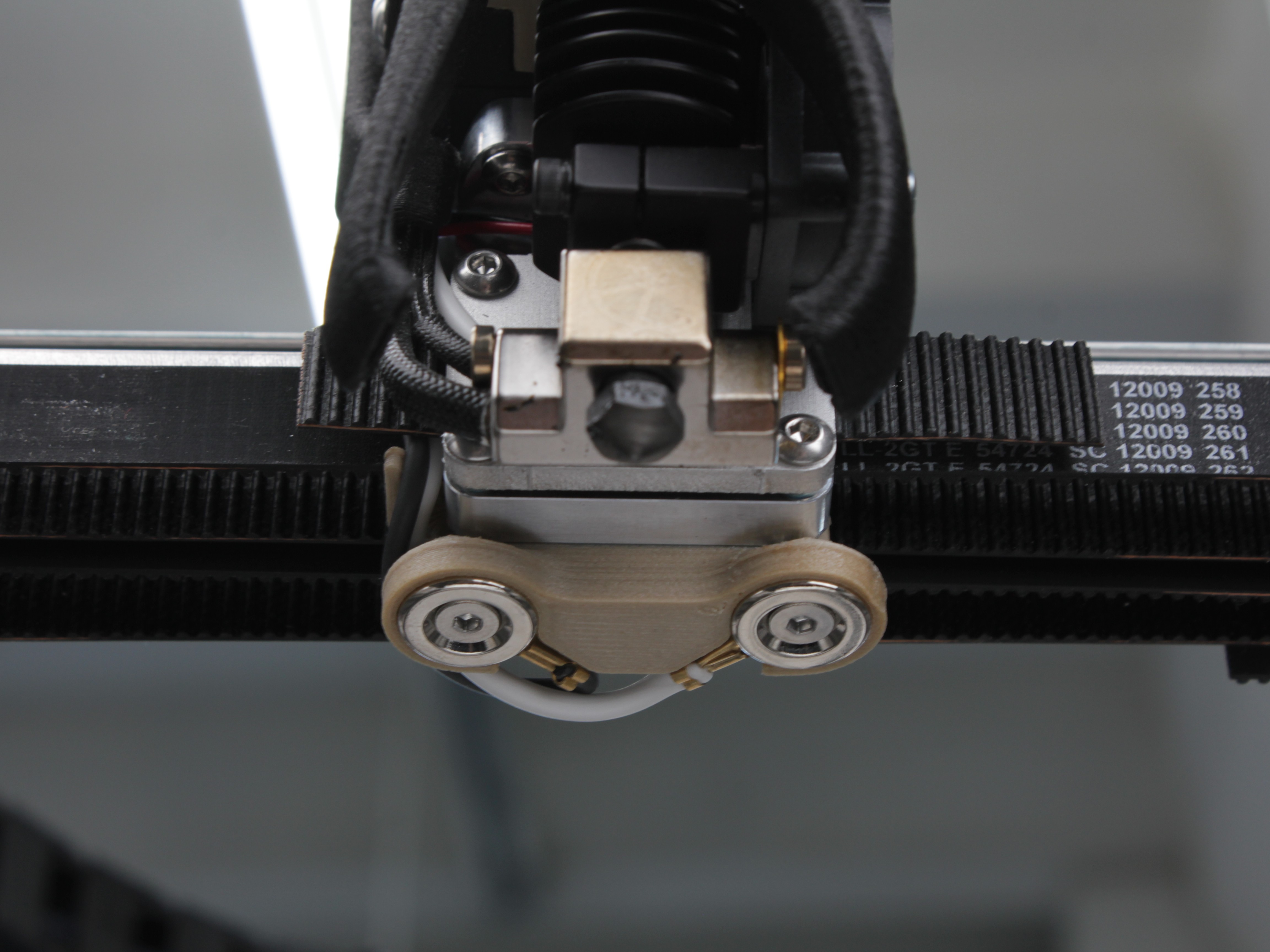
The Tool 0 (left) toolhead carries both legs through its two magnets: one magnet is wired to signal, the other to ground. The magnets are conductive, so they are both the electrical contacts and the mechanical latch.
- Probe attached: the probe's two magnets bridge the toolhead magnets, and its normally-closed switch links signal → ground → value 0. Click the plunger (or remove the probe) and the switch opens → value 1000.
- Nozzle as a contact: the signal leg is also wired to the T0 nozzle / heater block, and the build plate is ground. So touching the T0 nozzle to the bed connects signal → ground in exactly the same way the probe does.
The Tool 1 (right) toolhead has no probe and no magnets – only a single signal wire to its hotend, so its nozzle can also be touched to the grounded bed for contact sensing.
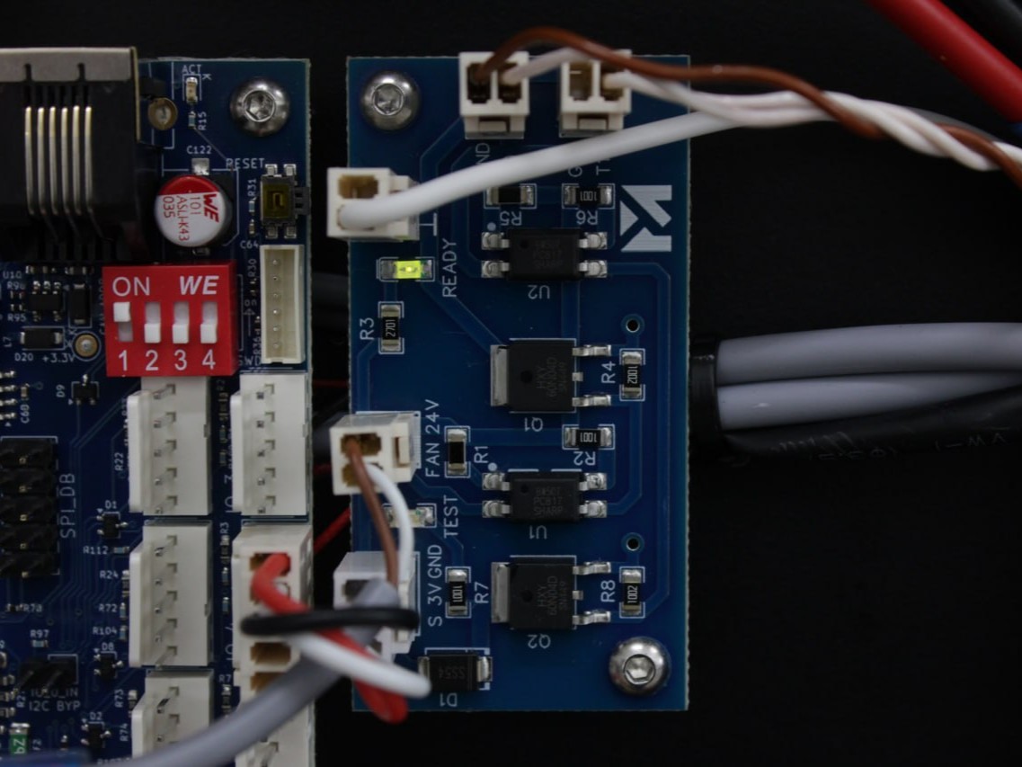
The optocoupler PCB at the rear powers this circuit only when a measurement is needed (Z-homing, auto-calibration) and keeps it off the rest of the time for ESD protection. It reports the state to the mainboard and drives its own two indicator LEDs.
Two ways the printer measures Z
- With the probe – the plunger touches the build plate; the switch opens at contact and the printer records the height. Used for Z-homing and mesh.
- With the nozzle – during auto-calibration the nozzle itself touches the bed, and signal-to-ground contact marks the moment it reaches the plate. Used for tool offsets.
The everyday way to read the probe state is the Web Interface probe value (0 or 1000). The optocoupler PCB also has two indicator LEDs, but they are at the rear of the machine, so you only use them if the back is already open. Both are documented in the Probe State Reference at the bottom of this page.
1. Running the Z-Probe Self-Test
The printer has a built-in self-test macro that checks the Z-Probe circuit. Run this first to diagnose electrical issues.
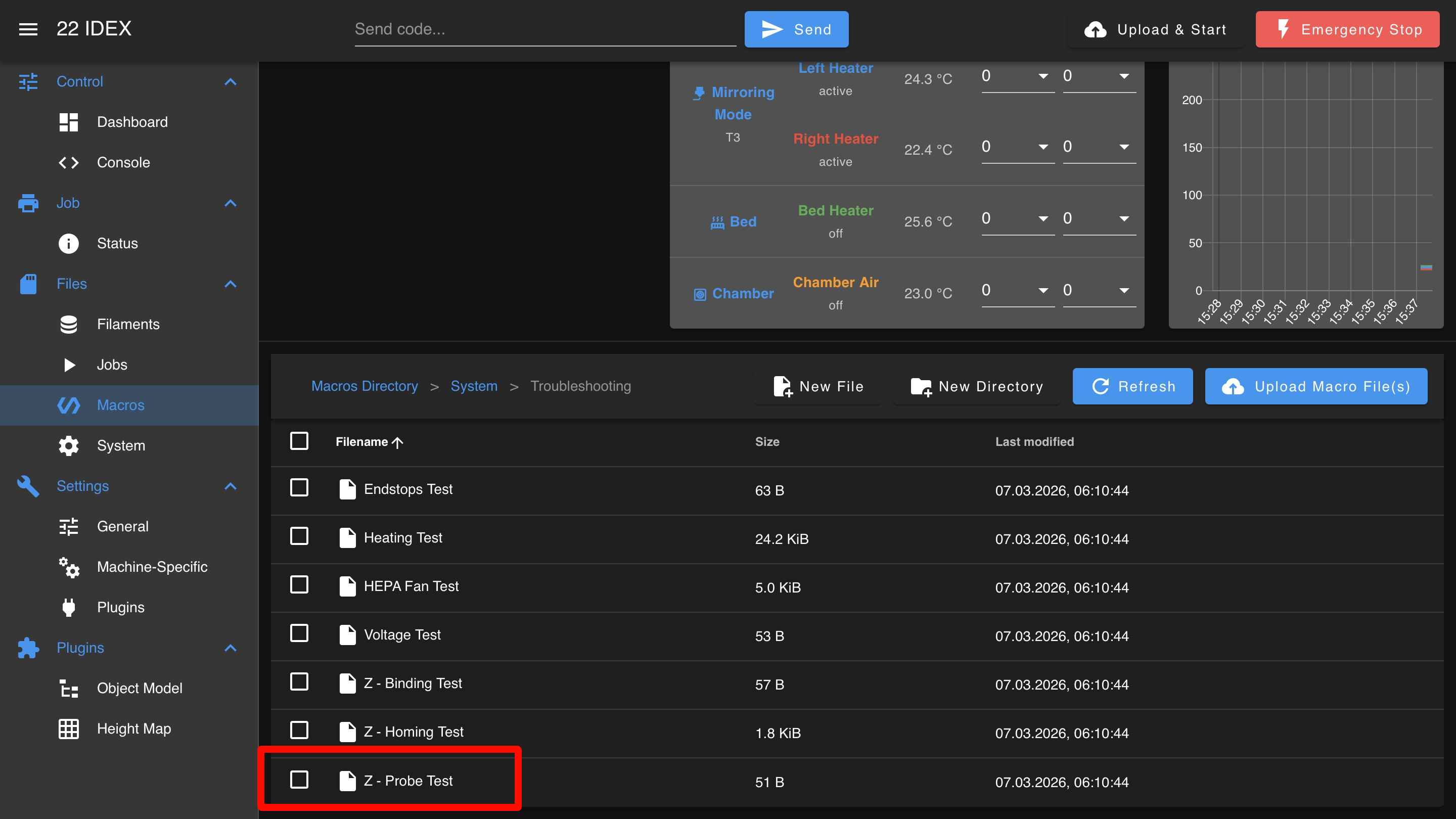
To launch the test: open the Web Interface > Macros > System > Troubleshooting > Z - Probe Test.
The test verifies:
- Open circuit – probe circuit reads 1000 when probe is removed
- Nozzle-to-bed contact – signal-to-ground connection works for left and right toolheads
- Probe attachment – probe is detected when attached to magnets (value changes to 0)
- Probe click – plunger press breaks the circuit (value changes from 0 to 1000)
If any test fails, the macro will indicate which part of the circuit has a problem:
- Short circuit (probe reads 0 when detached) → go to 3. Short Circuit
- Nozzle contact failed (left, right, or both) → go to 4. Nozzle Contact Failed
- Probe not detected (value stays 1000 when attached) → go to 5. Probe Not Detected
- Probe click failed (value stays 0 when pressed) → go to 6. Probe Click Failed
If all tests pass but the probe still fails to pick up or place, the problem is mechanical (pickup position or servo angle) – see 2. Probe Pickup and Placement Issues below.
2. Probe Pickup and Placement Issues
If the self-test passes but the probe still fails during auto-calibration or Z-homing, the pickup position or servo angle needs recalibration.
Symptoms:
- The probe does not get picked up – the toolhead does not reach the dock station at the back of the machine.
- The servo rotates to the wrong angle and the probe cannot be grabbed.
- The probe gets knocked off during placement.
Dialogs you may see during pickup or placement:
| Dialog | When it appears | Most likely cause |
|---|---|---|
| "Probe Pickup Failed" | Running Pick the Probe, or pickup during homing | Pickup position / servo angle off, or the probe is not in the dock (if the circuit is fine) |
| "Probe Removal Failed" / "Probe Still Attached" | After placing the probe back (during the macro / during homing) | Probe did not seat in the dock, or a short keeps the circuit closed (see 3. Short Circuit) |
| "Z-Probe Not Calibrated" | Pickup or placement | Calibration data is missing – run Probe Calibration (below) |
Two further messages – "Probe not detected at start of placing" and "Probe was not detected at the dock after placing" – are event-log warnings only (no dialog); check the Console if a probe is lost mid-move.
If the self-test passes but you still get a "Probe Pickup Failed" or "Probe Removal Failed" / "Probe Still Attached", the fault is mechanical (pickup position or servo angle), not electrical.
What knocks the pickup out of alignment (it does not usually drift on its own):
- Mechanical work on the toolhead, or removing/refitting the endstops shifts the X/Y pickup position (usually X, and it is the more noticeable one). Re-run Probe Calibration to set it.
- Servo angle drift – with age, or as the servo warms up, the holder may rotate slightly off. A small fine-tune of the pickup angle fixes it.
- Dead servo – if the holder does not rotate at all, the servo has failed and needs replacement.
Solution: Run the Probe Calibration macro (Macros > System > Calibration > Z Probe > Probe Calibration in the Web Interface). It walks you through the X pickup position and the servo angle – a few minutes. See the Z-Probe Calibration Guide for the full procedure.
Before running calibration, also check:
- Clear any filament strands, debris, or tools from the dock area and the pickup path.
- Verify the dock is securely mounted and has not shifted.
3. Scenario A – Short Circuit
What happened: The probe circuit reads as closed (value 0) even though the probe is physically removed. The signal leg is connected to ground somewhere it should not be – with no probe attached and no nozzle touching the bed, the two legs should be open (see How the Z-Probe Works).
The printer also detects this automatically during homing and shows a "Z-Probe Short Circuit" dialog with three buttons: Run Z-Probe Test, Conductive Filament (enables the heat-break retraction described in 7. Conductive Filament Residue), and Dismiss. If your filament is carbon-fiber-filled or ESD-grade, pressing Conductive Filament turns on the automatic end-of-print purge that prevents this.
Symptoms outside the test:
- Homing or auto-calibration stops early with the "Z-Probe Short Circuit" dialog. The
attachedcheck/detachedchecksafety checks catch the short before any probing move, so the nozzle does not crash into the bed – the printer refuses to probe instead. - The printer behaves as if the probe is already attached when it is not.
- Web Interface probe value stuck at 0 with no probe attached.
Work through these checks in order:
- Check for conductive filament. Carbon-fiber-reinforced and ESD materials (CF-Nylon, CF-PEEK, CF-PAEK, CF-Ultem) conduct electricity. A strand of conductive filament bridges the metal extruder gears – which are grounded through the frame – to the hot block, which carries the probe signal. That connects signal to ground and shows up as a short. Unload the filament and clean the extruder, nozzle, and magnets thoroughly, then re-run the self-test. If the short clears but you later get inconsistent or false probe readings, conductive residue may remain inside the nozzle – see 7. Conductive Filament Residue – False Z-Probe Readings for the full solution.
Power off before inspecting toolhead wiring (steps 2–5)
Steps 2–5 below require inspecting wiring and internal components. Turn off the printer and unplug it from the power outlet. Wait at least 60 seconds for the capacitors to discharge. Let the hotend cool to room temperature before touching it.
-
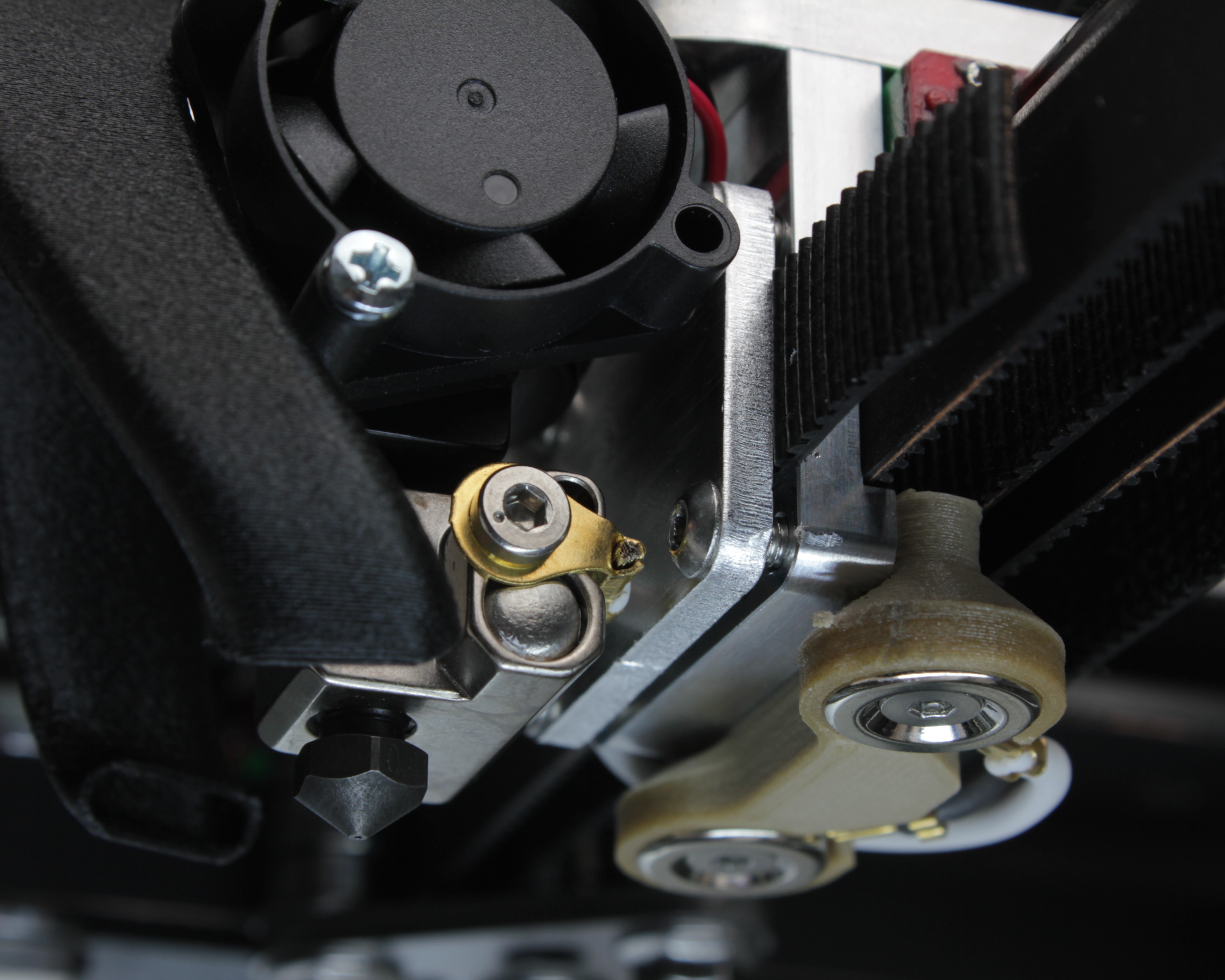
Check the Tool 0 signal lug. The crimp lug/terminal on the T0 heater block carries the probe signal. If it or its wire touches the grounded aluminum bracket (or any other frame metal), signal is shorted to ground. This is the most common mechanical cause – and easy to happen, because the heat break is twistable and can rotate the lug into the bracket. Bend or reposition the wire to create clearance.
-
Inspect wiring. Follow the probe wires from the toolhead magnets back to the distribution block/PCB. Look for damaged insulation, pinched cables, or wear. Also check fan, temperature sensor, and heater wires – frayed insulation on any nearby wire can short to the probe circuit.
-
Check connections. Lightly tug each Z-Probe wire at the distribution block terminals. For quick-connect terminals, release the wire using the appropriate method for your terminal type, inspect for fraying or corrosion, and reinsert firmly.
-
(Advanced) Check the PEEK interface screws. Remove the PEEK interface (the part joining the extruder motor to the hotend). The screws securing the hotend should be slightly recessed – not protruding past the mounting surface. Protruding screws can cause intermittent shorts. Check both T0 and T1.
-
If the short persists after all checks, contact support with the Web Interface probe value and the self-test results.
4. Nozzle Contact Failed
What happened: The probe circuit did not detect contact when you touched the nozzle to the build plate. The test tells you which side failed – Left (T0), Right (T1), or both.
- Both sides failed – the common factor is the shared ground: check the build-plate ground connection (both nozzle tests return through the grounded bed), or a broken signal return upstream.
- One side failed – the signal path for that toolhead. On T0 the signal runs to the heater block and the signal magnet; on T1 it is a single signal wire to the hot block (T1 has no probe and no magnets).
Work through these checks:
- Make sure you are using something conductive. The screwdriver, wrench, or wire must be metal. Touch it firmly from the nozzle tip to the build plate surface – the contact must be solid.
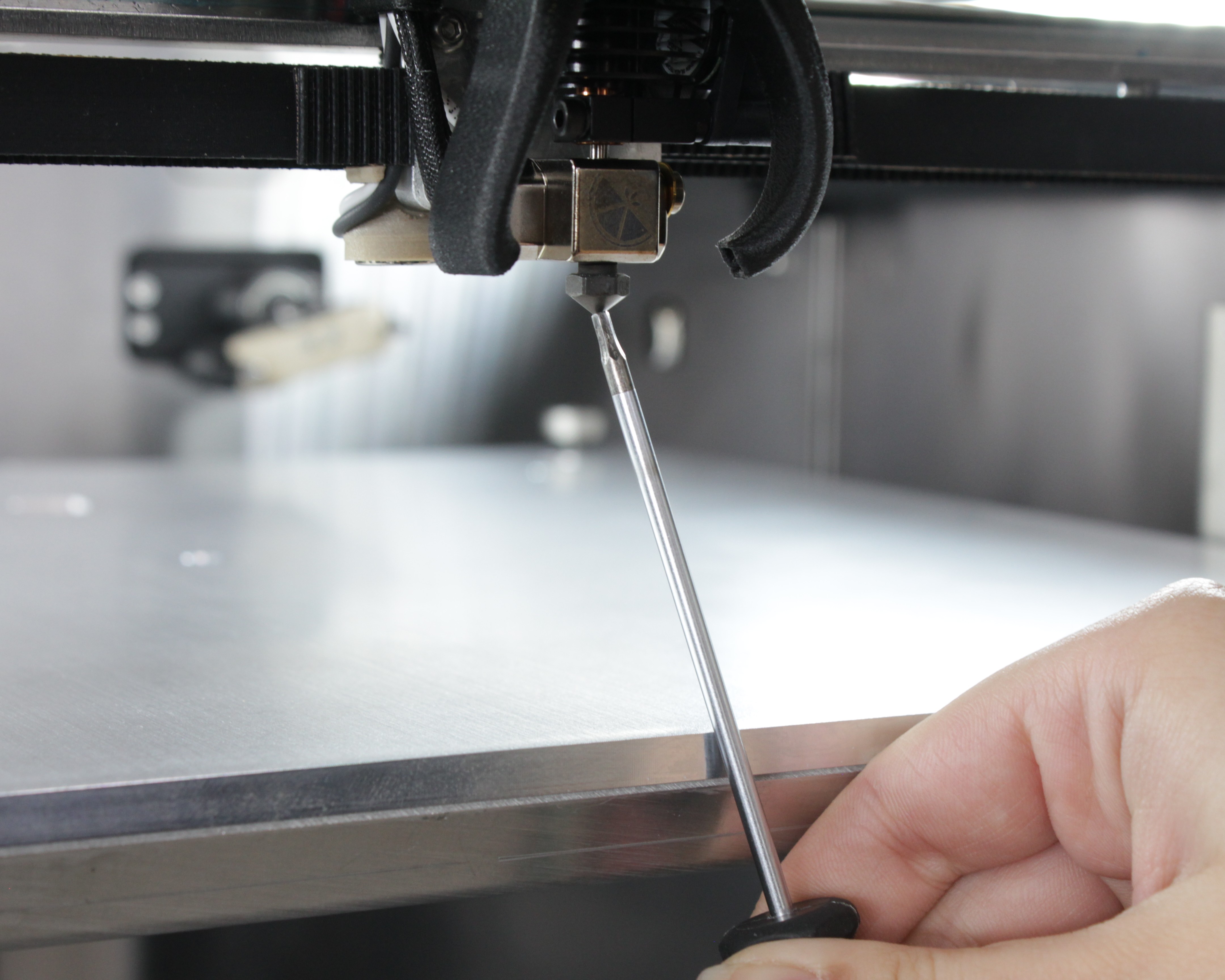
- Re-run the test. Sometimes a light touch does not register. Press firmly and hold for a moment.
Power off before inspecting wiring (step 3)
Step 3 requires inspecting wiring. Turn off the printer and unplug it from the power outlet. Wait at least 60 seconds for the capacitors to discharge.
-
Inspect the signal wiring on the failed side. On T0, trace the signal wire from the heater block / toolhead magnet back to the distribution block; on T1, trace the single signal wire from the hot block. Check for loose, broken, or corroded connections. If both sides failed, check the build-plate ground wire instead.
-
Test with a magnet bypass (T0 only). T0 has two magnets; T1 does not, so this test applies to the left tool. To tell whether a T0 failure is in the toolhead wiring or the probe, lay a wrench or screwdriver across both T0 magnet contacts to short them together. If the Web Interface value changes from 1000 to 0, the T0 wiring is fine – the problem is the probe. If it does not change, the T0 signal/ground wiring or magnet connections need reseating or repair.
-
Check build plate wiring (if both sides failed). Follow the build plate ground wire to the distribution block and verify the connection is secure.
-
Contact support if the problem persists. Include the self-test results and which side(s) failed.
5. Scenario B – Probe Not Detected
What happened: You attached the Z-Probe to the toolhead magnets, but the circuit did not detect it. The value stayed at 1000 (open circuit).
Symptoms outside the test:
- The printer picks up the probe but does not recognize it.
- Web Interface value stays at 1000 even with the probe attached.
- Dialog during homing: "Z-Probe Not Connected" (after a failed auto-pickup) or "Probe Pickup Failed". Event log: "Probe not connected after pickup attempt".
Work through these checks:
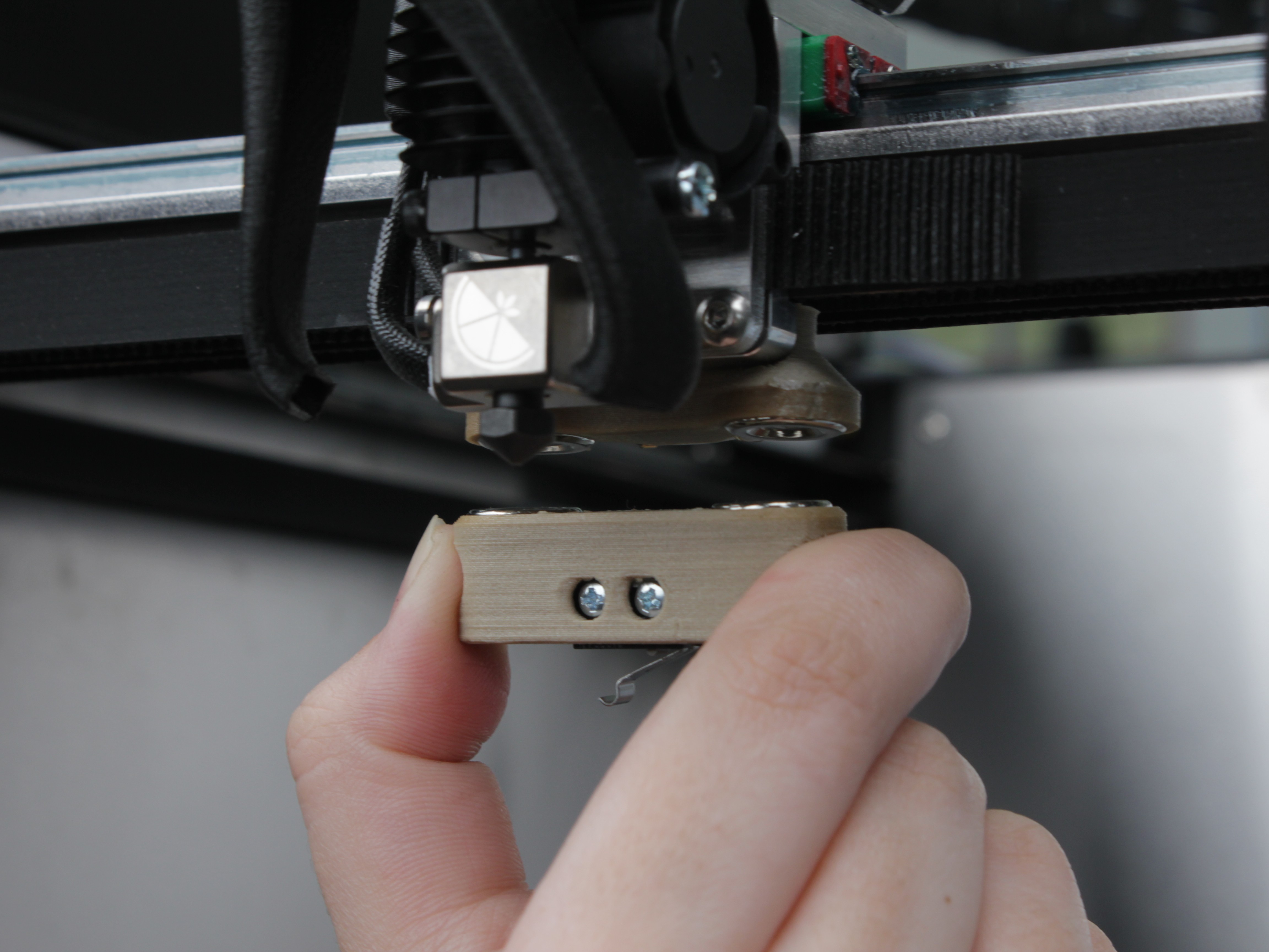
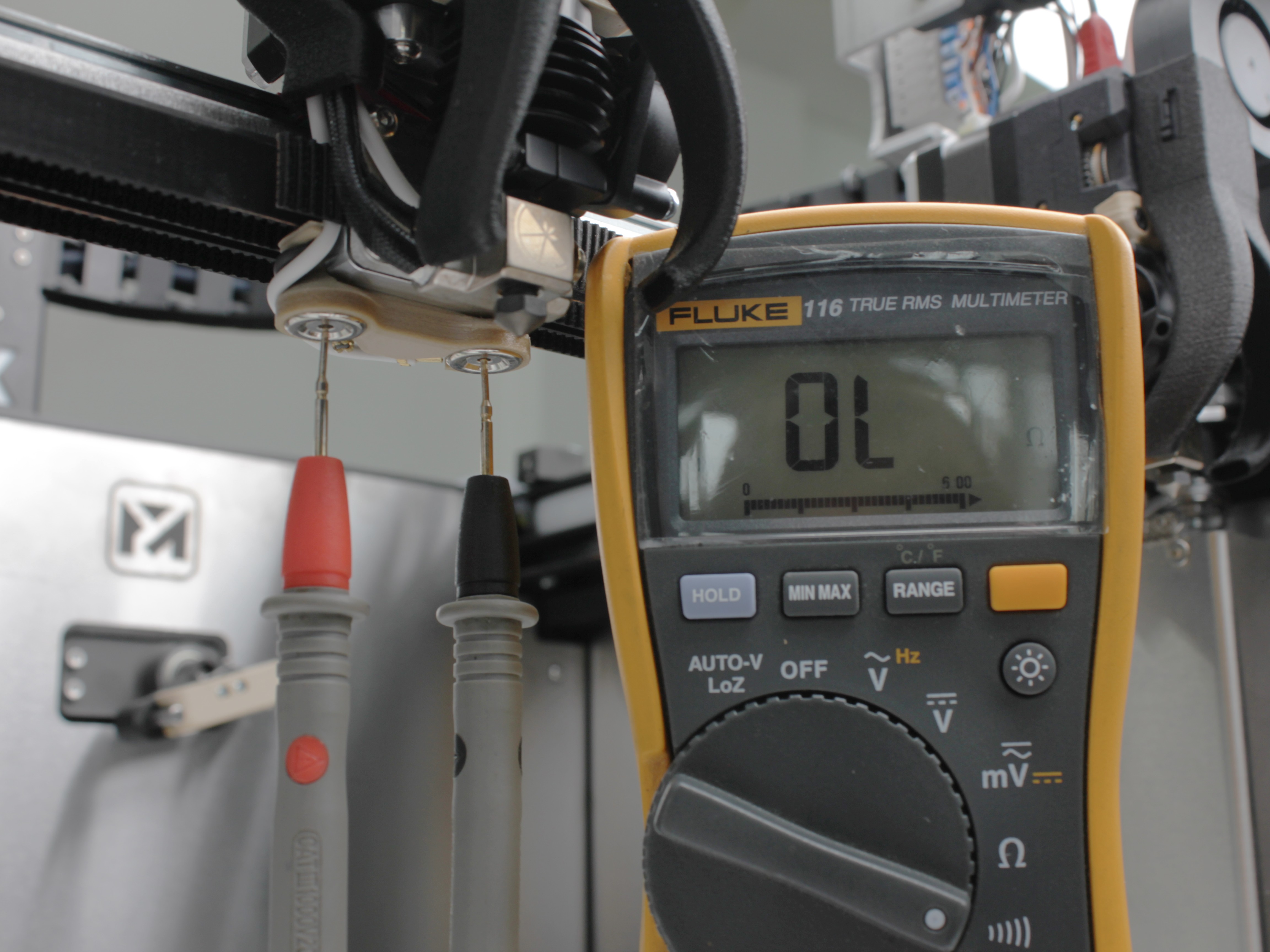
- Test the Z-Probe body with a multimeter. Set the multimeter to continuity mode. Place the probes on the two magnet contacts on the probe body:
- Plunger up (not triggered): multimeter should beep (continuity – closed circuit).
- Plunger pressed (triggered): no beep (open circuit).
- If this fails, the Z-Probe Sensor Assembly is defective and needs replacement.
-
Test the probe mechanically. Press the plunger gently – you should hear and feel a crisp click. Mushy, sticky, or silent = faulty probe.
-
Bypass the probe – short the magnets directly. If you don't have a multimeter, re-run the self-test. When it asks you to attach the probe, instead of attaching the probe, lay a wrench or screwdriver across both magnet contacts on the toolhead. If the value changes to 0, your toolhead wiring is good and the Z-Probe itself is faulty – replace the probe. If the value does not change, the toolhead wiring is the problem (recheck connections, reseat wires at the distribution block).
-
Clean the magnets. Wipe both the toolhead magnets and the probe body magnets with a clean, dry cloth. Remove filament residue, oil, or debris.
-
Check magnet seating. Using a 2 mm hex screwdriver (hex wrench), gently check the tightness of the screws on the Z-Probe Magnet Set – two magnets on the probe body and two magnets on the toolhead. Loose magnets cause intermittent or failed connections.
-
Contact support if the probe is still not detected.
6. Probe Click Failed
What happened: The probe is attached and detected (value 0), but pressing the plunger does not register. The value does not change from 0 to 1000 when clicked.
This means the internal switch in the Z-Probe is defective. The probe needs replacement.
Before replacing, double-check:
- Press the plunger firmly – you should hear a crisp click.
- If the click is mushy or silent, the switch mechanism is worn out.
Contact support to order a replacement probe.
7. Conductive Filament Residue – False Z-Probe Readings
Conductive filaments – carbon-fiber-filled (CF-Nylon, CF-PEEK, CF-PAEK, CF-Ultem), metal-filled, and ESD materials – can leave electrically conductive residue inside the nozzle after a print. When this residue melts and bridges electrical contact points during the next Z-homing or mesh compensation cycle, the printer registers false probe triggers and produces incorrect Z-height readings.
Symptoms:
- Z-probe gives inconsistent readings after printing with conductive filament.
- First layer is too high or too low despite correct calibration.
- Probe triggers at random heights during mesh compensation.
- Self-test passes but probing behavior is unreliable.
Prevention – Extended Retraction Feature
The firmware includes an extended retraction feature that automatically retracts filament after every print to prevent conductive residue from remaining in the heat zone.
When enabled, it:
- Lowers the active nozzle temperature by 50 °C.
- Waits for the nozzle to reach the lower temperature.
- Retracts 150 mm of filament (in addition to the standard 40 mm retraction in
end.g).
This pulls conductive material out of the heat break and prevents false probe readings.
Configuring Retraction Behavior
You can configure the retraction behavior through the Web Interface: Macros > System > Settings > Job End > Tools Unload.
The dialog "Retract Filament from Tool After Print" offers three modes:
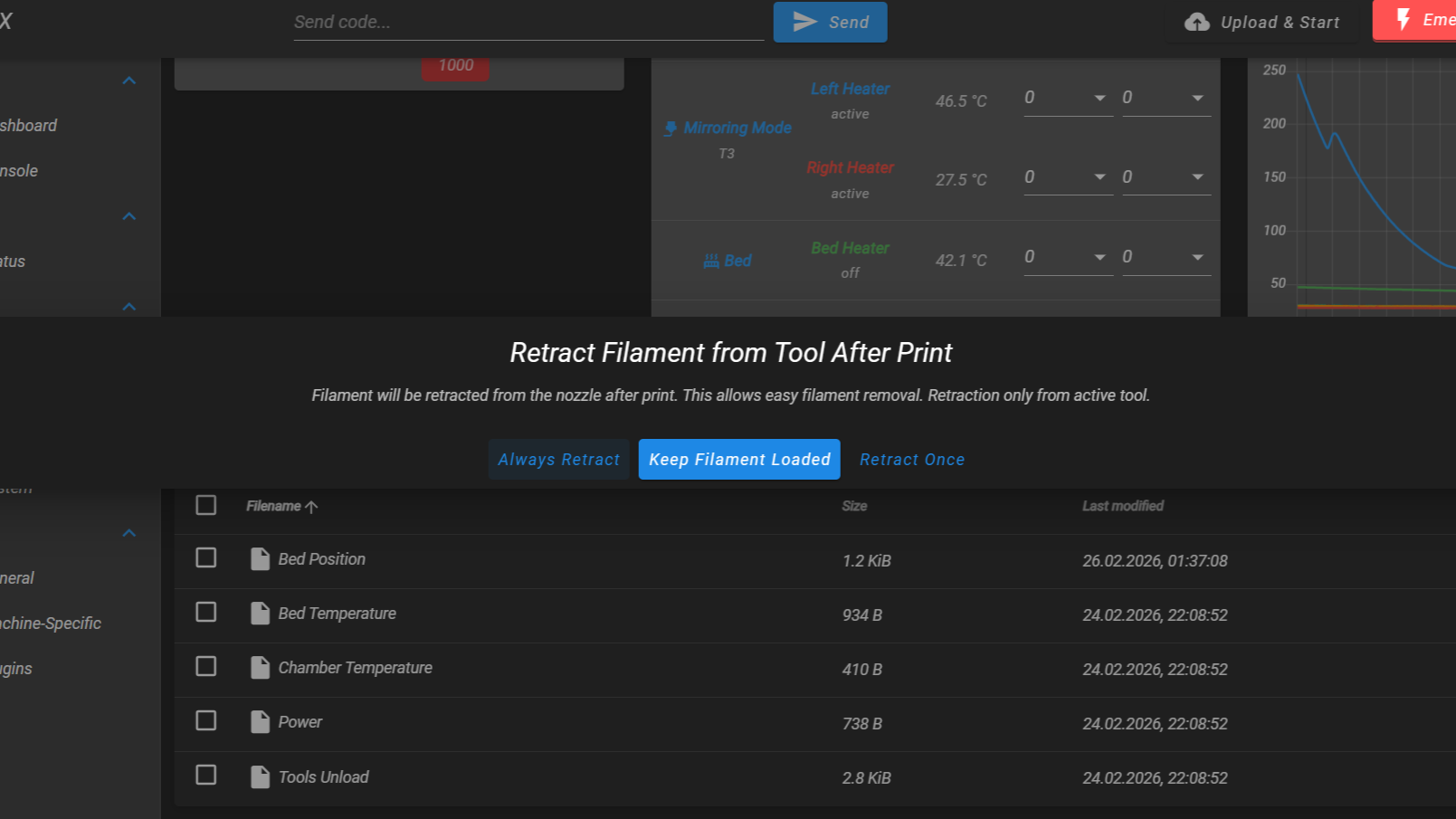
| Mode | Description |
|---|---|
| Always Retract | Extended retraction runs after every print. Lowers temperature by 50 °C and retracts 150 mm. Recommended for conductive filaments. |
| Keep Filament Loaded | No extended retraction. Only the standard 40 mm retraction in end.g runs. |
| Retract Once | Extended retraction runs only once (next print), then automatically switches to "Keep Filament Loaded". Useful for one-off material swaps. |
For regular conductive filament printing, select Always Retract.
If the Problem Persists
If false readings continue even with extended retraction enabled:
- Perform a manual cold pull – heat the nozzle to printing temperature, insert filament, let it cool to 100–120 °C, then pull firmly to extract residue from the heat break.
- Clean the nozzle tip and toolhead magnets with a dry cloth to remove any external residue.
- If the nozzle is severely contaminated, consider replacing it or cleaning it with a torch (steel nozzles only).
- Re-run the Z-Probe Self-Test to verify the circuit is working correctly.
- Contact support if the problem persists.
8. Manual Probe Diagnosis – Is It the Probe or the Circuit?
If you want to determine whether the problem is with the Z-Probe body (the mechanical switch) or the toolhead circuit (wiring, magnets, optocoupler) without running the full self-test, follow these steps.
Before starting: Enable the probe detection circuit. Open the Web Interface > Macros > System > Calibration > Z Probe > Enable Probe (or send M42 P4 S1 in the console). The circuit is now live, so the probe value in the Web Interface reflects the real state (and, if you have the rear panel open, the green LED on the optocoupler PCB turns on).
Test A – Attach the Probe
Attach the Z-Probe to the toolhead magnets. Check the probe value in the Web Interface:
- Value changes from 1000 to 0 – the circuit detects the probe. Proceed to Test B.
- Value stays at 1000 – the circuit does not detect the probe. Skip to Test C.
Test B – Click the Probe
With the probe attached and reading 0, press the probe plunger firmly. The value should change from 0 to 1000 while the plunger is pressed, and return to 0 when released.
- Value changes 0 → 1000 → 0 – the probe switch is working correctly. The problem is elsewhere (likely mechanical – see 2. Probe Pickup and Placement Issues).
- Value stays at 0 – the probe's internal switch is defective. The switch does not open the circuit when pressed. Replace the Z-Probe. Contact Vision Miner support.
Test C – Short the Toolhead Magnets
This test isolates whether the problem is in the toolhead circuit or in the Z-Probe body.
Remove the Z-Probe from the toolhead. Using the included 2.5 mm hex screwdriver, bridge the two magnet contacts on the toolhead probe holder – lay the screwdriver across both magnets so it touches each one simultaneously.
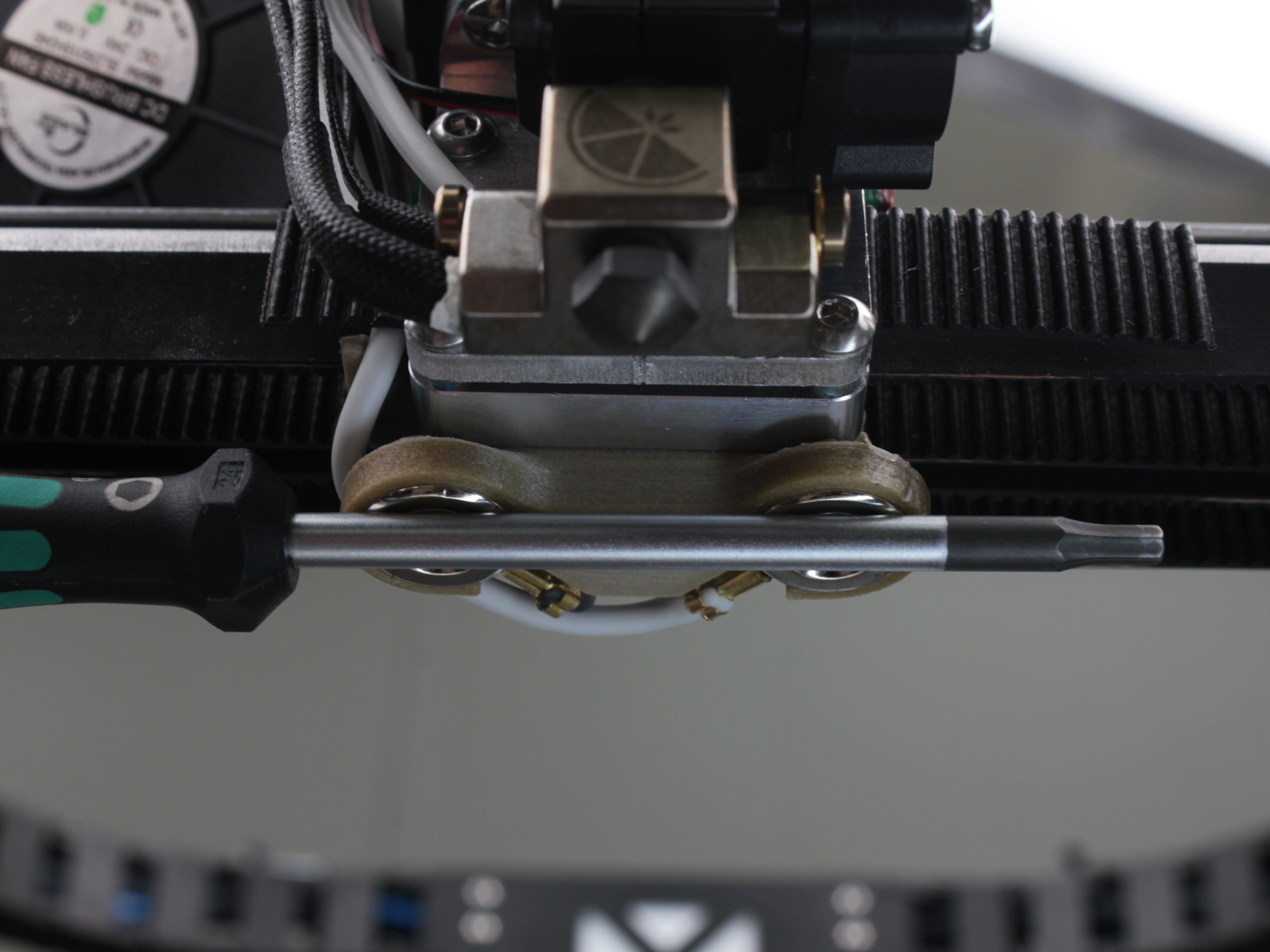
Check the probe value in the Web Interface:
- Value changes from 1000 to 0 – the toolhead circuit is working correctly. The problem is the Z-Probe body (defective switch or poor magnet contact on the probe side). Replace the Z-Probe. Contact Vision Miner support.
- Value stays at 1000 – the toolhead circuit has a problem. Check the magnet connections, wiring from the magnets to the distribution block, and the optocoupler PCB. See 4. Nozzle Contact Failed for detailed wiring inspection steps.
Useful Macros
The printer firmware includes several Z-Probe macros in the Web Interface. Here is a quick reference:
| Macro | Location in Web Interface | What it does |
|---|---|---|
| Z - Probe Test | Macros > System > Troubleshooting | Self-test – checks the full probe circuit step by step |
| Probe Calibration | Macros > System > Calibration > Z Probe | Adjusts X position and servo angle for pickup/placement |
| Pick the Probe | Macros > System > Calibration > Z Probe | Picks up the probe from the dock |
| Place the Probe | Macros > System > Calibration > Z Probe | Places the probe back in the dock |
| Enable Probe | Macros > System > Calibration > Z Probe | Activates the probe relay (enables detection circuit) |
| Disable Probe | Macros > System > Calibration > Z Probe | Deactivates the probe relay (disables detection circuit) |
Probe State Reference
Use this section for detail while working through the steps above. The Web Interface probe value is the everyday indicator – you read it from the front of the machine. The optocoupler-PCB LEDs show the same state but sit on the board at the rear, so they only help once you already have the back open.
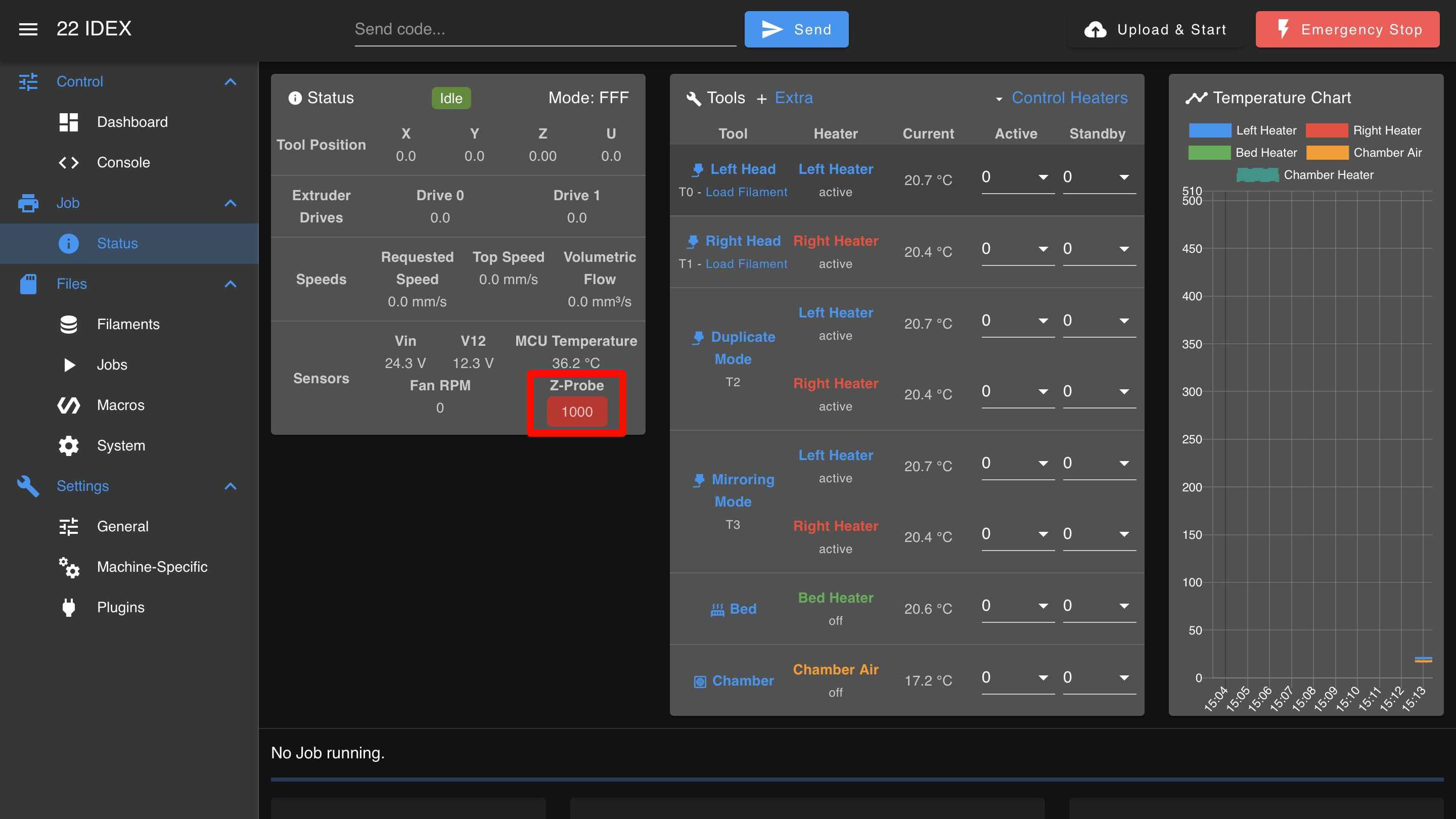
Web Interface Value
Check the probe value in the Web Interface under Machine Status or General:
- 1000 – probe detached, triggered, or circuit disabled (open circuit)
- 0 – probe attached and not triggered (closed circuit)
Note the probe value before contacting support
Tell support the Web Interface probe value in each state (probe docked, probe attached, plunger pressed) along with your self-test results – it speeds up diagnosis significantly.
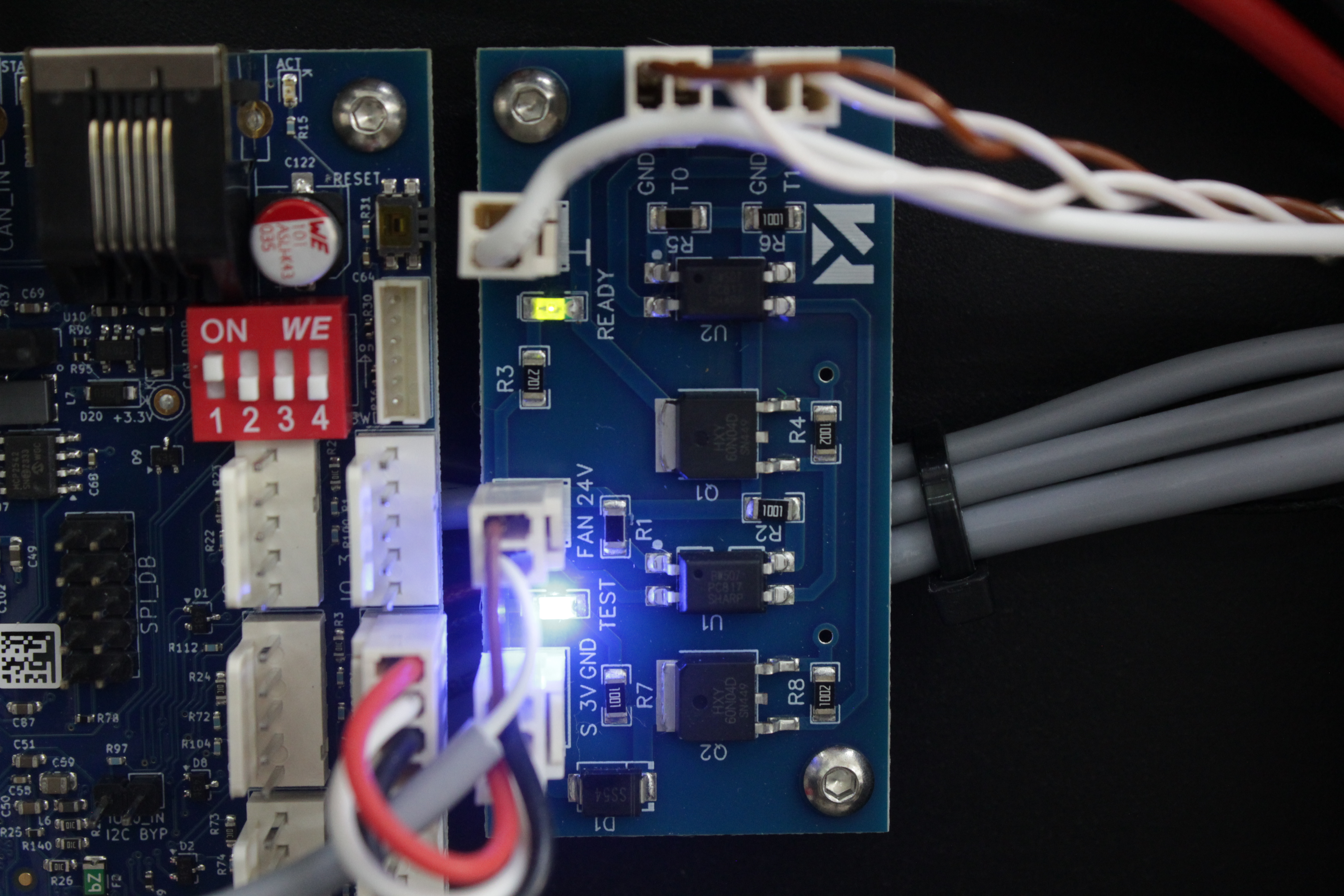
LED Indicators (rear PCB – advanced)
The optocoupler PCB has two LEDs that mirror the probe state, but they are on the board at the rear of the machine – you have to look behind it, so most diagnosis uses the Web Interface value above instead. They are also separate from the RGBW chamber lighting the self-test uses.
🟢 Green LED – Circuit Enabled
- On when the firmware activates the probe detection circuit (during homing or probing).
- Off at all other times.
🔵 Blue LED – Probe Detected
- On when the Z-Probe is attached and the internal switch is closed (not triggered).
- Off when the probe is triggered (plunger pressed) or not attached.
| Z-Probe State | Green | Blue |
|---|---|---|
| Circuit disabled, probe not attached | Off | Off |
| Circuit enabled, probe not attached | 🟢 | Off |
| Circuit enabled, probe attached, not triggered | 🟢 | 🔵 |
| Circuit enabled, probe attached, triggered | 🟢 | Off |
| Circuit disabled, probe attached, not triggered | Off | 🔵 |
| Circuit disabled, probe attached, triggered | Off | Off |
FAQ
Support
If you could not find an answer here, reach out to our support team.